#08186
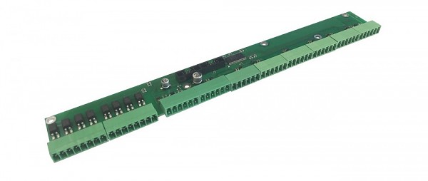
Dry contacts board IN/OUT (Vutlan VTX40)
A complementary module for VT900 and VT960 DC master units.
| Technical specifications | |
|---|---|
| Dry contacts |
x32 dry contact inputs, x8 isolated dry contact outputs |
| Connection | BH-10 |
| Supply includes |
BH-10 bus cable, x8 terminals (6P 3.5mm), x2 terminals (8P 3.5mm), x5 screws |
| Dimensions (LHW) | 241 x 35 x 11 mm |
#08235
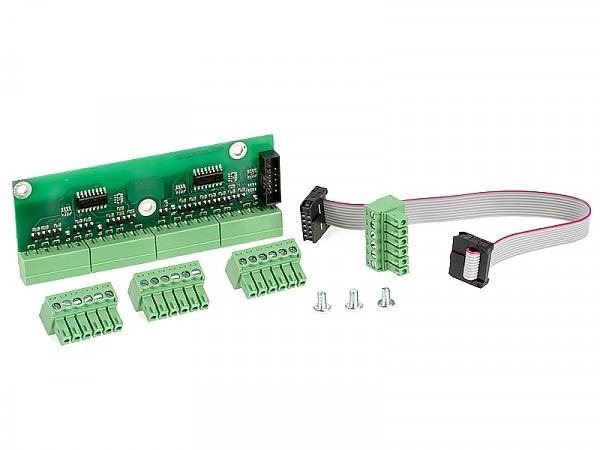
Dry contacts module (Vutlan VT16)
Complementary module for moin units, can be connected to 16 dry contacts.
Dedicated for SC8100, VT8101, VT8110, VT800.
Dedicated for SC8100, VT8101, VT8110, VT800.
| Technical specifications | |
|---|---|
| Dry contacts | 16 |
| Contact outputs | 3.5 mm |
| Features | |
| Installation | On the PCB there are 3 mounting holes for fastening to the surface using screws 3 mm inside of any master unit. |
| Connection | Jack IDC2-10 is connected to IDC2-10 input of master unit. Determination of PCB's type and connection occur automatically. Monitoring system allows connection of up to 16 dry contacts. |
| Supply includes |
PCB, 10-wired IDC2 cable (10cm), 3 screws M3. |
| Net weight | 80g |
| Dimensions (LHW) | 70x10×25mm |
#08916
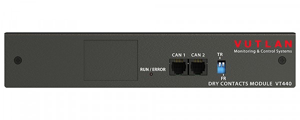
Dry contacts unit (Vutlan VT440)
Allows to increase the number of dry contacts connected to any Vutlan monitoring unit. Adds 32 dry contacts (or 64 with VT32 module). Can be connected to any CAN port.
| Number of dry contacts | 32 - 64 |
|---|---|
| Contact outputs | 3.5mm |
| Max contact distance | 500m |
| Number of CAN ports |
2 (1 input, 1 output) |
| Mounting |
The unit includes two 19" mounting angles for mounting inside the rack. Alternatively, there are 2 mounting holes on the bottom of the case for fastening on the wall. Fasten the unit, connect CAN inputs to the input of the previous CAN unit or of the monitoring unit. The red LED lights up. Match the bus terminators of the CAN units. Switch terminator TR in ON position on the monitoring unit and on the last CAN unit, TR on intermediate CAN units are in Off (1,2) position. Maximum 8 CAN units, sensors and/or devices can be on one CAN bus. |
| Inventory |
Unit, 3-pair shielded patch cable RJ-12 2 m length, screw 3.5 x 16 mm, fastener 2-sided, rubber feet, 19" mounting angles. |
| Net weight | 0.5 kg |
| Dimensions (LHW) | 215×40×40mm |
#08116
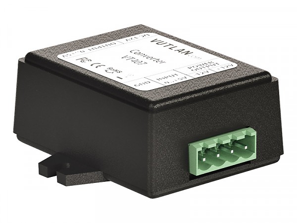
HAT sensor transducer 0-5V DC (Vutlan VT407)
The transducer is used together with HAT-100Q1 current transducer.
| Power input |
12V DC, 1A |
|---|---|
| Input | RJ-12 / RJ-11 |
| Power Consumption | 100mW |
| Operating temperature | -10°C ÷ 80°C |
| Operating humidity |
5% ÷ 95%, non-condensing |
| Net weight | 150g |
| Dimensions (LHW) | 68 × 47 x 26 mm |
| Max distance | 50m |
#08117 AC current transducer Vutlan HAT-100Q1
#03105
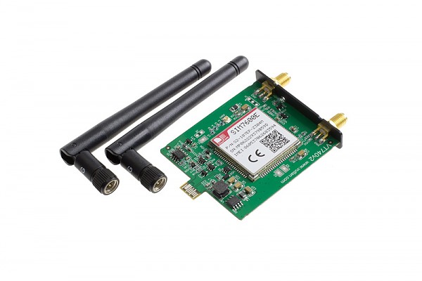
Internal LTE, GPS modem (Vutlan VT740)
4G LTE slot modem for Vutlan monitoring units. Allows to receive and send SMS messages. Provides Ethernet over 4G LTE. Power-cycling is an embedded function.
Can be used together with VT335t, VT825t/VT825tt, VT855t/VT855tt & VT604/VT608.
Antennas included.
Can be used together with VT335t, VT825t/VT825tt, VT855t/VT855tt & VT604/VT608.
Antennas included.
#03099
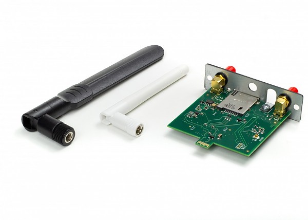
Internal LTE, GPS modem (Vutlan VT790)
4G LTE slot modem for Vutlan monitoring units. Allows to receive and send SMS messages. Provides Ethernet over 4G LTE. Power-cycling is an embedded function.
Can be used together with VT960i & VT960ii.
Antennas included.
Can be used together with VT960i & VT960ii.
Antennas included.
#08370
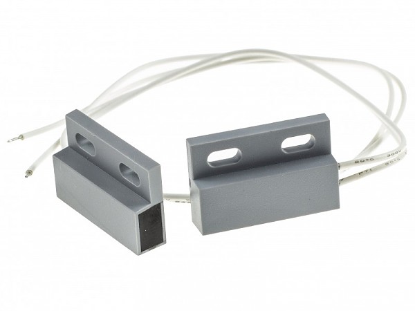
Magnet access sensor (Vutlan KMS-30)
The sensor made for checking whether the doors or windows have been opened/closed.
| Installation | Insert the terminal into "Dry contact Input" of Vutlan monitoring system. |
|---|---|
| Supply includes |
magnet sensor, 4x screws M3 12.5mm, 2x stickers. |
| Max. distance | 500m |
| Power consumption | 6W |
| Dimensions (WHL) | Two 60x18x18mm compact devices |
#03120
Modbus RTU Slot Extension (Vutlan VT485m)
Allows to monitor up to 32 Modbus RTU devices/meters/sensors. The maximum distance of a daisy chain is up to 1000 meters. Each metered value of a Modbus device is addressed individually using input registers and is shown by the system as virtual sensors. You can configure thresholds and icon representations for these elements.
It can be used with VT335t, VT336t, VT825t, and VT855t monitoring systems. A slot PCB board can be inserted inside the monitoring unit while the unit is in operation. Has an internal termination and by default, it is switched ON (if required can be turned off).
It can be used with VT335t, VT336t, VT825t, and VT855t monitoring systems. A slot PCB board can be inserted inside the monitoring unit while the unit is in operation. Has an internal termination and by default, it is switched ON (if required can be turned off).
#08368
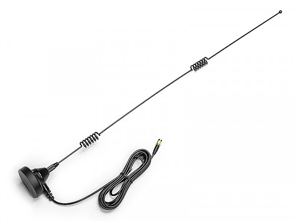
Omni-directional GSM antenna 7 dBi (Vutlan VT6604)
| Omnidirectional gain | 7 dBi |
|---|---|
| Frequency range | 890-960 / 1710-1890 / 1920-2170 MHz |
| Impedance | 50 Ω |
| Connector | SMA(M) |
| Cable | RG174 |
| Mounting Possibilities | Has A Magnet At The Bottom |
| Cable lenght | 3m |
| Temprature | Min. -10° C - Max.80° C |
| Size | ∅50 x 520 mm |
| Manufacturer | Vutlan |
#08917
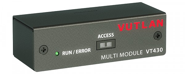
Rack control unit (Vutlan VT430)
The module has a PIR sensor for rack door control, 2 dry contacts and a humidity sensor. Connected to a CAN port, it allows further CAN chain connection.
Sensors and contacts appears in the system automatically.
Max. distance from the monitoring unit is 300 meters.
Sensors and contacts appears in the system automatically.
Max. distance from the monitoring unit is 300 meters.
| Technical specifications | |
|---|---|
| Measured humidity range | 10-95% RH |
| Accuracy | 5% RH |
| PIR sensor disrance | 30mm |
| Number of dry contacts | 2 |
| Number of CAN ports | 2 |
| Maximum distance from the appliance | 300m |
| Features | |
| Installation |
There are 4 mounting holes on the bottom of the case for fastening. Fasten the unit, connect CAN inputs to the input of the previous CAN unit or of the monitoring unit. |
| Connection | Sensor's jack RJ-12 is connected to CAN input of any system unit or to a CAN output of another sensor using RJ-12 patch cable. Determination of sensor's type and connection occur automatically. |
| Supply includes |
Unit, shielded patch cable RJ-12, 2 screws and 2 nuts M6, sticker, dry contacts connector.. |
| Net weight | 0.2 kg |
| Dimensions (LHW) | 89×27×36mm |
Page 4 of 7
|

