 VUTLAN Products |
|
Server Rooms Monitoring Systems |
|
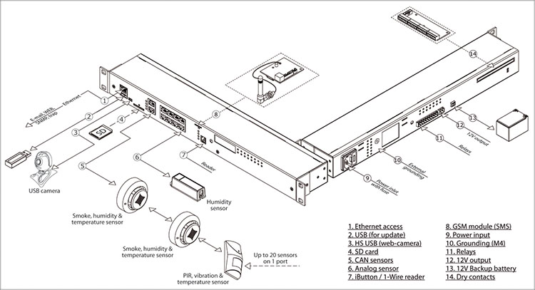
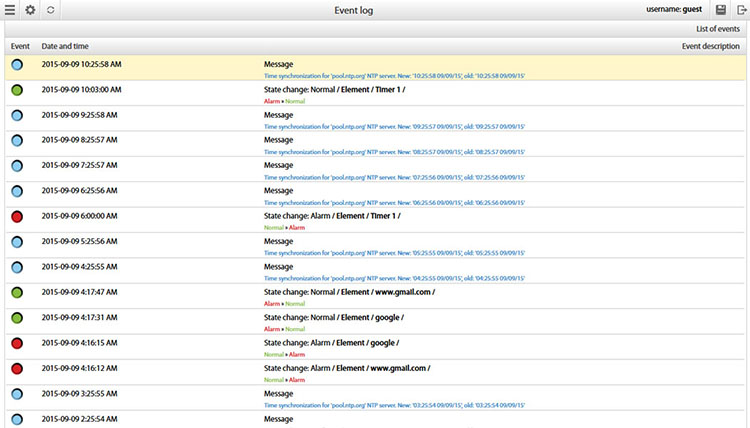
VUTLAN provides IP monitoring and power management solutions for enterprises and small businesses. Monitoring Systems and IP Power Distribution ranges are designed for large data centres, server rooms, web hosting facilities, 19 inch telecommunication racks etc. Environmental monitoring in the server rooms, on the telecommunication nodes, in data centers et cetera is of great importance to many if not to all companies. What are the indoor temperature and humidity, what happens to the air conditioning or fans, whether the line voltage has a huge impact on the reliability of the equipment and the service life of servers, switches, and routers. If you have the only rack with a couple of ups and two three servers, you need to install a small monitoring unit with 5-6 sensors, enter your notifications and logic and may be to connect an inexpensive USB cam. Built-in web server and video server allows you to view logs and events at your facility, the logic when properly installed will allow the monitoring system to accept most decisions, for example, to shut down servers at high temperature or at failure of air conditioning or fans, or in case of fire, etc. and to warn user with any notification or SMS (if GSM modem is installed). If you have a set of facilities and requires a scalable, easy-to-install solution for monitoring a distributed network, then you must either apply extension units and sensors that allow to gather information from wide area, or when there are absolutely great distances between nodes and objects, it is possible to use SNMP applications that allow to collect information from multiple remote sites and can be stored in any database, if necessary, to use this information by appropriate authorities. It is also important to use monitoring systems with easy scalability and a wide range of sensors,with longlife-warranty period at a reasonable prices. All this ensures the equipment from VUTLAN, the most modern manufacturer of IP monitoring systems! Manufacturer's website: http://www.vutlan.com |
- Computer Network Accessories
-
- » MAIN UNITS#03113
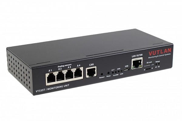
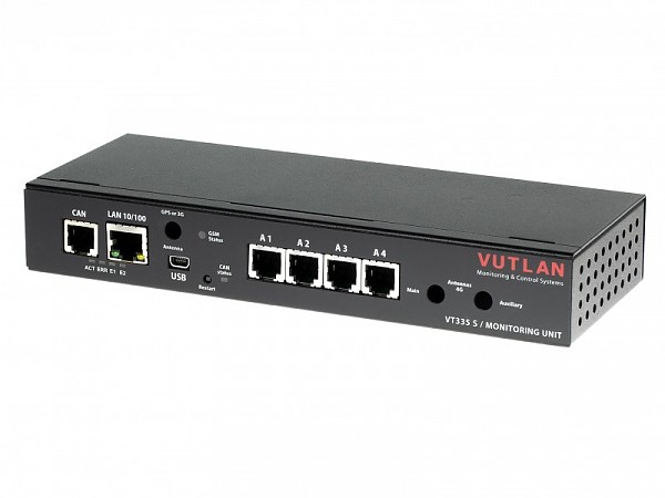
MINI Monitoring unit; 4x analog; 1 x CAN (Vutlan VT335t)
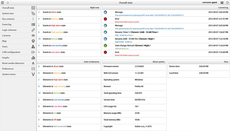
The unit is used for environmental monitoring (e.g. temperature, humidity, voltage, leakage, smoke, airflow). It is also used as an I/O controller (e.g. door control, fans, generator, control panels, UPS, circuit breakers, and alarms). Can connect 150 physical sensors. Can use up to 1000 elements - notifications, triggers, timers, logic schemes, sensors, and dry contacts. Has a built-in Web interface with virtual sensors, logic schemes, different types of notifications, and control panels. Has a slot for #03105 VT740 LTE slot modem (sold separately) for an ethernet connection reservation. Has two power inputs for power reservation (i.e. battery plus main power supply).REMOTE CONTROL IP monitoring Web,
SNMP,
SMS (LTE modem art. VT740 is ordered separately!)Sensors control Administrative 3-level control of sensors using login INTERFACE & PROTOCOL SUPPORT Interface Access via any Internet browser. LAN Ethernet 10/100Mbit Network protocols DHCP; HTTP; HTTPS; DynDNS; SNMP v1,
v2c,
v3; SMTP; FTP; Syslog; TLS; RADIUS; OpenVPN; SSL; NTPOS Linux v.6.2 Processor 720 MHz RAM 128MB Software Built-in software for events processing. Alert type E-mail,
FTP log,
Syslog,
SMTP,
SNMP Traps,
SMS (LTE modem VT740 is ordered separately!),
Web-to-SMSA maximum number of "mail to" recipients 20 A maximum number of "SMS to" recipients in an SMS notification 20 Pings Built-in ping LEDs LINK,
CAN,
ACT,
E1,
E2,
ERRORClock Built-in clock with time synchronization Watchdog Built-in watchdog timer POWER Power req 2x12V DC Power consumption 10W Power reservation 12V,
built-in voltage monitorINLETS/OUTLETS Ethernet 10/100Mbit Micro USB AB USB 2.0 micro Analog port 4x6P4C for connecting any analog sensor. CAN BUS 1 x 6P6C for connecting up to 32 CAN sensors (over 12 sensors,
regeneration of the signal is required using the CAN # 03880 power module). Fuse protection on each line.Alarm relay 2 x 12V 0.25A alarm port for VT103 Alarm Beacon (#08264) or VT105 (#08344) Dry contact inputs 4 x dry contacts input EXTERNAL MEMORY Micro SD card Micro SD card slot (SDXC up to 512 Gb) FEATURES Installation desktop (19" cabinet with VT122t) Dimensions (WxHxD) 180mm × 35mm × 80mm Net weight 0.7 kg Working temperature Min. -10° C - Max. 80° C Supply includes Monitoring unit,
12VDC power supply,
RJ45 cord,
Micro USB cable adapter,
plug 1x6P, 3.5mm,
plug 1x3P, 3.81mm,
plug 1x2P, 3.81mm,
manual,
warranty,
4 self-adhesive rubber legs,
plugs.Warranty 3 years
#03865MINI Monitoring unit; 4x analog; 1 x CAN 48V DC (Vutlan VT335 S DC)
The control unit of the Vutlan environmental parameters monitoring system.
The device is equipped with four ports for analog sensors, one CAN digital port, four potential-free contacts, two alarm signaling contacts, built-in temperature sensor and allows to connect a USB camera. 48V DC version.
It can be additionally equipped with LTE module #08318REMOTE CONTROL IP monitoring Web,
SNMP,
SMTPSensors control Administrative 3-level control of sensors using login INTERFACE & PROTOCOL SUPPORT Interface Access via any Internet browser. LAN Ethernet 10/100Mbit Network protocols Built-in HTTP server,
SNMP agent,
SMTP agent,
manageable logic. Uses FTP link for updating current software version.Processor ARM926-300 MHz OS Linux 2.6.38 RAM 64Mb ROM 512 Mbit NAND Flash Software Built-in software for events processing. Alert type FTP,
syslog,
SMTP or SNMPPings Built-in ping LEDs power,
network,
alarms;Clock Built-in clock with time synchronization Watchdog Built-in watchdog timer POWER Power input 48V DC Power consumption 6W Power reservation 12V,
built-in voltage monitorINPUTS/OUTPUTS Ethernet 100Mbit Mini USB AB USB 2.0 HS Analog port 4x 6p4c for connection of any analog sensor. CAN port 1x6p6c (max 12 CAN sensors) Dry contacts 4x 12V outlets 2x 0.25A FEATURES Installation Desktop or 19" (with #082222 19" holder / bracket for VT335 S monitoring unit - ordered separately) Dimensions (LxHxW)206 x 33.1 x 79.4 mm Net weight 1,2 kg Warranty 3 years
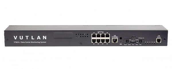
#03115Monitoring unit 19" 1U; 8x analog; 1x CAN; 16x dry contact inputs (Vutlan VT825t)
The unit is used for environmental monitoring (e.g. temperature, humidity, voltage, leakage, smoke, airflow). It is also used as an I/O controller (e.g. door control, fans, generator, control panels, UPS, circuit breakers, alarms). Can use up to 1000 different elements - notifications, triggers, timers, logic schemes, sensors, dry contacts. Has built-in Web interface with virtual sensors, logic schemes, different types of notification, and control panels.
Order options:
1 power inlet (VT825t) or 2 power inlets (VT825tt), providing a redundant power supply for A&B power distribution.REMOTE CONTROL IP monitoring Web,
SNMP,
SMS (LTE modem art. VT740 is ordered separately!)Sensors control Administrative 3-level control of sensors using login INTERFACE & PROTOCOL SUPPORT Interface Access via any Internet browser. LAN Ethernet 10/100Mbit Network protocols HTTP; HTTPS; DynDNS; SSL; SNMP v1,
v2c,
v3; SMTP; FTP; Syslog; RADIUS; OpenVPNOS Linux 6.2 Processor Cortex A7 720MHz Total CPU cores 2 RAM 128MB Software Built-in software for events processing. Alert type FTP,
syslog,
SMTP or SNMP,
SMS (LTE modem #03105 is ordered separately)A maximum number of "mail to" recipients 20 A maximum number of "SMS to" recipients in an SMS notification 20 Pings Built-in ping LEDs CAN,
ACT,
E1,
E2,
Error,
Relays R1 and R2Clock Built-in clock with time synchronization Watchdog Built-in watchdog timer The maximum amount of sensors 130 The maximum amount of elements 1000 USB cameras x1 IP cameras x4 POWER Power req 90-240V,
IEC C14,
Fuse 1A or DC (24V/48V)Power consumption 10W Power reservation 12V,
built-in voltage monitorINLETS/OUTLETS Ethernet 100Mbit USB USB 2.0 Type A Mini USB AB USB 2.0 HS Analog port 8x6P4C for connecting any analog sensor. CAN BUS 1 x 6P6C for connecting up to 32 CAN sensors (over 12 sensors,
regeneration of the signal is required using the CAN # 03880 power module). Fuse protection on each line.Relay outputs 2 ports Alarm relay 2 x 12V 0.25A alarm port for VT103 Alarm Beacon (#08264) or VT105 (#08344) Dry contact inputs 16 x dry contacts input EXTERNAL MEMORY Micro SD card Micro SD card slot (SDXC up to 512 Gb - saving logs,
record video,
run software,
databases and scripts)FEATURES Installation 19" cabinet or desktop Dimensions (WxHxD) 440mm × 44mm × 90mm Net weight 1.5 kg Working temperature Min. -10° C - Max. 80° C Supply includes Monitoring unit,
power cable 240V,
RJ45 cord,
manual,
warranty,
4 self-adhesive rubber legs,
plugs,
19" mounting angles.Warranty 3 years
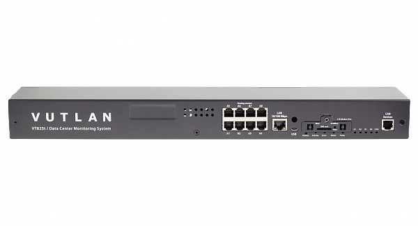
#03116Monitoring unit 19" 1U; 8x analog; 1x CAN; 16x dry contact inputs (Vutlan VT825tt)
The unit is used for environmental monitoring (e.g. temperature, humidity, voltage, leakage, smoke, airflow). It is also used as an I/O controller (e.g. door control, fans, generator, control panels, UPS, circuit breakers, alarms). Can use up to 1000 different elements - notifications, triggers, timers, logic schemes, sensors, dry contacts. Has built-in Web interface with virtual sensors, logic schemes, different types of notification, and control panels.
Order options:
1 power inlet (VT825t) or 2 power inlets (VT825tt), providing a redundant power supply for A&B power distribution.REMOTE CONTROL IP monitoring Web,
SNMP,
SMS (LTE modem art. VT740 is ordered separately!)Sensors control Administrative 3-level control of sensors using login INTERFACE & PROTOCOL SUPPORT Interface Access via any Internet browser. LAN Ethernet 10/100Mbit Network protocols HTTP; HTTPS; DynDNS; SSL; SNMP v1,
v2c,
v3; SMTP; FTP; Syslog; RADIUS; OpenVPNOS Linux 6.2 Processor 720MHz Total CPU cores 2 RAM 128MB Software Built-in software for events processing. Alert type FTP,
syslog,
SMTP or SNMP,
SMS (LTE modem #03105 is ordered separately)A maximum number of "mail to" recipients 20 A maximum number of "SMS to" recipients in an SMS notification 20 Pings Built-in ping LEDs CAN,
ACT,
E1,
E2,
Error,
Relays R1 and R2Clock Built-in clock with time synchronization Watchdog Built-in watchdog timer The maximum amount of sensors 130 The maximum amount of elements 1000 USB cameras x1 IP cameras x4 POWER Power req 2x IEC C14 90-240V 1A fuse or 2x DC (24V/48V) or 1x AC + 1x DC Power consumption 10W Power reservation 12V,
built-in voltage monitorINLETS/OUTLETS Ethernet 100Mbit USB USB 2.0 Type A Mini USB AB USB 2.0 HS Analog port 8x6P4C for connecting any analog sensor. CAN BUS 1 x 6P6C for connecting up to 32 CAN sensors (over 12 sensors,
regeneration of the signal is required using the CAN # 03880 power module). Fuse protection on each line.Relay outputs 2 ports Alarm relay 2 x 12V 0.25A alarm port for VT103 Alarm Beacon (#08264) or VT105 (#08344) Dry contact inputs 16 x dry contacts input EXTERNAL MEMORY Micro SD card Micro SD card slot (SDXC up to 512 Gb - saving logs,
record video,
run software,
databases and scripts)FEATURES Installation 19" cabinet or desktop Dimensions (WxHxD) 440mm × 44mm × 90mm Net weight 1.5 kg Working temperature Min. -10° C - Max. 80° C Supply includes Monitoring unit,
power cable 240V,
RJ45 cord,
manual,
warranty,
4 self-adhesive rubber legs,
plugs,
19" mounting angles.Warranty 3 years
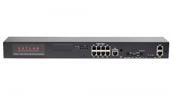
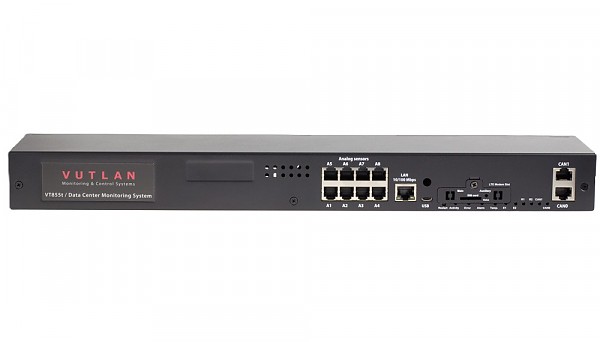
#03117Monitoring unit 19" 1U; 8x analog; 1x CAN; 32x dry contact inputs (Vutlan VT855t)
VT855t / Data Center Monitoring System is used for environmental monitoring (e.g. temperature, humidity, voltage, leakage, smoke, airflow). It is also used as an I/O controller (e.g. door control, fans, generator, control panels, UPS, circuit breakers, and alarms). Can use up to 1000 different elements - notifications, triggers, timers, logic schemes, sensors, dry contacts. Has a built-in Web interface with virtual sensors, logic schemes, different types of notifications, and control panels.
Order options:
1 power inlet (VT825t) or 2 power inlets (VT825tt), providing a redundant power supply for A&B power distribution.REMOTE CONTROL IP monitoring Web,
SNMP,
SMS (LTE modem art. VT740 is ordered separately!)Sensors control Administrative 3-level control of sensors using login INTERFACE & PROTOCOL SUPPORT Interface Access via any Internet browser. LAN Ethernet 10/100Mbit Network protocols HTTP; HTTPS; DynDNS; SSL; SNMP v1,
v2c,
v3; SMTP; FTP; Syslog; RADIUS; OpenVPNOS Linux 6.2 Processor Cortex A7 1GHz Total CPU cores 2 RAM 128MB Software Built-in software for events processing. Alert type FTP,
syslog,
SMTP or SNMP,
SMS (LTE modem #03105 is ordered separately)A maximum number of "mail to" recipients 20 A maximum number of "SMS to" recipients in an SMS notification 20 Pings Built-in ping LEDs CAN,
ACT,
E1,
E2,
Error,
Relays R1 and R2Clock Built-in clock with time synchronization Watchdog Built-in watchdog timer The maximum amount of sensors 150 The maximum amount of elements 1000 USB cameras x1 IP cameras x4 POWER Power req 90-240V,
IEC C14,
Fuse 1A or DC (24V/48V)Power consumption 10W Power reservation 12V,
built-in voltage monitorINLETS/OUTLETS Ethernet 100Mbit USB USB 2.0 Type A Mini USB AB USB 2.0 HS Analog port 8x6P4C for connecting any analog sensor. CAN BUS 2 x 6P6C for connecting up to 32 CAN sensors (over 12 sensors,
regeneration of the signal is required using the CAN # 03880 power module). Fuse protection on each line.Relay outputs 2 ports Alarm relay 2 x 12V 0.25A alarm port for VT103 Alarm Beacon (#08264) or VT105 (#08344) Dry contact inputs 32 x dry contacts input + 8 x dry contacts output EXTERNAL MEMORY Micro SD card Micro SD card slot (SDXC up to 512 Gb - saving logs,
record video,
run software,
databases and scripts)FEATURES Installation 19" cabinet or desktop Dimensions (WxHxD) 440mm × 44mm × 90mm Net weight 1.5 kg Working temperature Min. -10° C - Max. 80° C Supply includes Monitoring unit,
power cable 240V,
RJ45 cord,
manual,
warranty,
4 self-adhesive rubber legs,
plugs,
19" mounting angles.Warranty 3 years
#03118Monitoring unit 19" 1U; 8x analog; 2x CAN; 32x dry contact inputs (Vutlan VT855tt)
VT855tt / Data Center Monitoring System is used for environmental monitoring (e.g. temperature, humidity, voltage, leakage, smoke, airflow). It is also used as an I/O controller (e.g. door control, fans, generator, control panels, UPS, circuit breakers, and alarms). Can use up to 1000 different elements - notifications, triggers, timers, logic schemes, sensors, dry contacts. Has a built-in Web interface with virtual sensors, logic schemes, different types of notifications, and control panels.
Order options:
1 power inlet (VT855t) or 2 power inlets (VT855tt), providing a redundant power supply for A&B power distribution.REMOTE CONTROL IP monitoring Web,
SNMP,
SMS (LTE modem art. VT740 is ordered separately!)Sensors control Administrative 3-level control of sensors using login INTERFACE & PROTOCOL SUPPORT Interface Access via any Internet browser. LAN Ethernet 10/100Mbit Network protocols HTTP; HTTPS; DynDNS; SSL; SNMP v1,
v2c,
v3; SMTP; FTP; Syslog; RADIUS; OpenVPNOS Linux 6.2 Processor Cortex A7 1GHz Total CPU cores 2 RAM 128MB Software Built-in software for events processing. Alert type FTP,
syslog,
SMTP or SNMP,
SMS (LTE modem #03105 is ordered separately)A maximum number of "mail to" recipients 20 A maximum number of "SMS to" recipients in an SMS notification 20 Pings Built-in ping LEDs CAN,
ACT,
E1,
E2,
Error,
Relays R1 and R2Clock Built-in clock with time synchronization Watchdog Built-in watchdog timer The maximum amount of sensors 150 The maximum amount of elements 1000 USB cameras x1 IP cameras x4 POWER Power req 2x IEC C14 90-240V 1A fuse or 2x DC (24V/48V) or 1x AC + 1x DC Power consumption 10W Power reservation 12V,
built-in voltage monitorINLETS/OUTLETS Ethernet 100Mbit USB USB 2.0 Type A Mini USB AB USB 2.0 HS Analog port 8x6P4C for connecting any analog sensor. CAN BUS 2 x 6P6C for connecting up to 32 CAN sensors (over 12 sensors,
regeneration of the signal is required using the CAN # 03880 power module). Fuse protection on each line.Relay outputs 2 ports Alarm relay 2 x 12V 0.25A alarm port for VT103 Alarm Beacon (#08264) or VT105 (#08344) Dry contact inputs 32 x dry contacts input + 8 x dry contacts output EXTERNAL MEMORY Micro SD card Micro SD card slot (SDXC up to 512 Gb - saving logs,
record video,
run software,
databases and scripts)FEATURES Installation 19" cabinet or desktop Dimensions (WxHxD) 440mm × 44mm × 90mm Net weight 1.5 kg Working temperature Min. -10° C - Max. 80° C Supply includes Monitoring unit,
power cable 240V,
RJ45 cord,
manual,
warranty,
4 self-adhesive rubber legs,
plugs,
19" mounting angles.Warranty 3 years
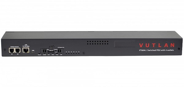
#03122Power distribution unit 2x analog, 1xCAN, 4x 230V (Vutlan VT604t)
The control unit supports 4 controlled 230V power sockets, 2 analog sensors, 2 potential-free sockets, 2 12V sockets and a LTE modem.
It allows remote switching on/off or restart for up to 4 connected devices.REMOTE CONTROL IP monitoring Web,
SNMP,
manual SMS (GSM modem art. VT740 #03105 is ordered separately!)Sensors control Administrative 3-level control of sensors using login INTERFACE & PROTOCOL SUPPORT Interface Access via any Internet browser. LAN Ethernet 10/100Mbit Network protocols HTTP; HTTPS; DynDNS; SSL; SNMP v1,
v2c,
v3; SMTP; FTP; Syslog; RADIUS; OpenVPNOS Linux 6.2 Processor dual-core CortexTM-A7 720 MHz / 128 MB Software Built-in software for events processing. Alert type FTP,
syslog,
SMTP or SNMP,
SMS (LTE modem art. VT740 #03108 is ordered separately!)Pings Built-in ping LEDs STATUS,
E1,
E2,
ERR,
4x OUTLETClock Built-in clock with time synchronization Watchdog Built-in watchdog timer POWER Power input IEC C13 240V x 16A. Fuse protection. Power output 4x C13 240V Power consumption 10W INPUTS/OUTPUTS Ethernet 100Mbit Mini USB AB USB 2.0 HS Analog port 2x 6P4C for connection of any analog sensor. CAN BUS 1 x 6P6C for connection of up to 32 CAN sensors on each BUS. Relay outputs 4x C13 230V/10A power sockets Built-in sensors Temperature sensor (1%),
Power supply voltage sensor (1%)Dry contacts input x2 12V outlets 2x 0.25A EXTERNAL MEMORY Micro SD card Micro SD card slot (SDXC up to 512 Gb - saving logs,
record video,
run software,
databases and scripts)FEATURES Installation 19" cabinet Dimensions (LxHxW) 440 x 44.45 (1U) x 79 mm Operating characteristics Humidity - Min. 5% - Max. 95% (Non-Condensing),
Temperature - Min. -10° C - Max.80° CNet weight 1,5 kg Supply includes EU Schuko C12 0.75 мм2 230V 10A cable,
IEC C13 Socket to IEC C14 Plug Power Cord,
Self-adhesive rubber foot 4 pcs,
Warranty card,
Short description and connection guide,
Patch cable RJ-45 1m,
Terminal plug 3 pins 3.5mm 1pcs,
Terminal plug 3 pins 3.81mm 1pcs,
Terminal plug 2 pins 3.81mm 1pc,
19" mounting brackets 2pcs,
Screws 6pcs M3 8mmWarranty 3 years Chosen accessories:
#03105 Internal LTE, GPS modem (Vutlan VT740)
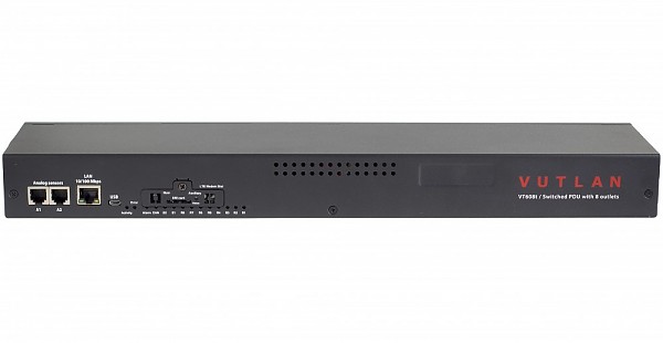
#03123Power distribution unit 2x analog, 1xCAN, 8x 230V (Vutlan VT608t)
The control unit supports 8 controlled 230V power sockets, 2 analog sensors, 2 potential-free sockets, 2 12V sockets and a LTE modem.
It allows remote switching on/off or restart for up to 8 connected devices.REMOTE CONTROL IP monitoring Web,
SNMP,
manual SMS (GSM modem art. VT740 #03105 is ordered separately!)Sensors control Administrative 3-level control of sensors using login INTERFACE & PROTOCOL SUPPORT Interface Access via any Internet browser. LAN Ethernet 10/100Mbit Network protocols HTTP; HTTPS; DynDNS; SSL; SNMP v1,
v2c,
v3; SMTP; FTP; Syslog; RADIUS; OpenVPNOS Linux 6.2 Processor dual-core CortexTM-A7 720 MHz / 128 MB Software Built-in software for events processing. Alert type FTP,
syslog,
SMTP or SNMP,
SMS (LTE modem art. VT740 #03108 is ordered separately!)Pings Built-in ping LEDs STATUS,
E1,
E2,
ERR,
4x OUTLETClock Built-in clock with time synchronization Watchdog Built-in watchdog timer POWER Power input IEC C20 240V x 16A. Fuse protection. Power output 8x C13 240V Power consumption 10W INPUTS/OUTPUTS Ethernet 100Mbit Mini USB AB USB 2.0 HS Analog port 2x 6P4C for connection of any analog sensor. CAN BUS 1 x 6P6C for connection of up to 32 CAN sensors on each BUS. Relay outputs 8x C13 230V/10A power sockets Built-in sensors Temperature sensor (1%),
Power supply voltage sensor (1%)Dry contacts input x2 12V outlets 2x 0.25A EXTERNAL MEMORY Micro SD card Micro SD card slot (SDXC up to 512 Gb - saving logs,
record video,
run software,
databases and scripts)FEATURES Installation 19" cabinet Dimensions (LxHxW) 440 x 44.45 (1U) x 79 mm Operating characteristics Humidity - Min. 5% - Max. 95% (Non-Condensing),
Temperature - Min. -10° C - Max.80° CNet weight 1,5 kg Supply includes EU Schuko C20 0.75 мм2 230V 10A cable,
2x IEC C13 Socket to IEC C14 Plug Power Cord,
Self-adhesive rubber foot 4 pcs,
Warranty card,
Short description and connection guide,
Patch cable RJ-45 1m,
Terminal plug 3 pins 3.5mm 1pcs,
Terminal plug 3 pins 3.81mm 1pcs,
Terminal plug 2 pins 3.81mm 1pc,
19" mounting brackets 2pcs,
Screws 6pcs M3 8mmWarranty 3 years Chosen accessories:
#03105 Internal LTE, GPS modem (Vutlan VT740)
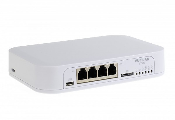
#03112Room monitoring unit; 4x analog; 1 x CAN (Vutlan VT325t)
Low-cost remote environmental monitoring unit for small IT rooms. Can monitor temperature, humidity, voltage, leakage, smoke, airflow, and other parameters. It is also used as an I/O controller (e.g. door control, fans, generator, control panels, UPS, circuit breakers, and alarms). Can signal an alarm, activate a siren, send an e-mail notification, or send an SNMP Trap. Can monitor up to 100 physical sensors. Can use up to 700 different elements - notifications, triggers, timers, logic schemes, sensors, and dry contacts. Has a built-in Web interface with virtual sensors, logic schemes, different types of notifications, and control panels. There are built-in servers and agents like HTTP, HTTPS, SNMP v1, 2c, 3, SMTP, Radius, Syslog, FTP, DHCP, and OpenVPN client.REMOTE CONTROL IP monitoring Web, SNMP Sensors control Administrative 3-level control of sensors using login INTERFACE & PROTOCOL SUPPORT Interface Access via any Internet browser. LAN Ethernet 10/100Mbit Network protocols DHCP; HTTP; HTTPS; DynDNS; SNMP v1,
v2c,
v3; SMTP; FTP; Syslog; TLS; RADIUS; SSL; NTP and OpenVPN clientOS Linux v.6.2 Processor 600 mHz RAM 128 Mb Software Built-in software for events processing. Pings Built-in ping LEDs LINK,
CAN,
ACT,
E1,
E2,
ERROR,
ALARMClock Built-in clock with time synchronization Watchdog Built-in watchdog timer Maximum number of sensors 70 Maximum number of elements 700 POWER Power req 1x 12V DC Power consumption 6 W INLETS/OUTLETS Ethernet 100Mbit Micro USB AB USB 2.0 micro Analog port 4x6P4C for connecting any analog sensor. CAN BUS –1x6P6C for connection of max 10 CAN. Fuse protection on each line.-- Alarm relay 2 x 12V 0.25A alarm port for VT103 Alarm Beacon (#08264) or VT105 (#08344) Dry contact inputs 2x digital inputs EXTERNAL MEMORY Micro SD card micro SD (SDXC do 64 Gb) FEATURES Installation desktop Dimensions (WxHxD) 150mm x 29mm x 100mm Net weight 0,5 kg Working temperature Min. -10° C - Max. 80° C Supply includes Monitoring unit,
12VDC power supply,
RJ-45 1m patch cable,
manual,
warranty,
plugs,
4 self-adhesive rubber legs.Warranty 3 years
- » ANALOG SENSORS#08244
AC voltage monitor (Vutlan VT520)
The sensor is made for measurement of 220-230V standard power supply or any other power sources in e.g. an outlet, on an extension cord or in a rack-mountable socket strip.Connection Plug 220V is put into the outlet necessary for measurement of 220V. Cable's USB connector must be connected to the USB output,
connector RJ-11 must be connected to an analog input of any system unit. Determination of sensor's type and connection occur automatically.Set includes Sensor and USB RJ-11 patch cable (1.8 m). Voltage measured 90-250V Accuracy of measurement 2% Max. distance m 100m Net weight 125g Dimensions (LHW) 63×66×40mm
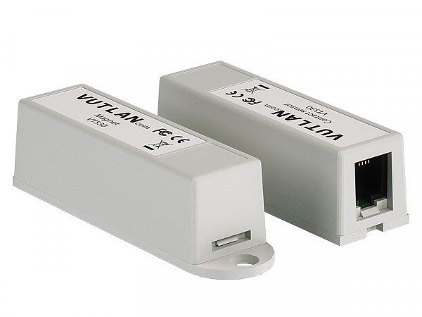
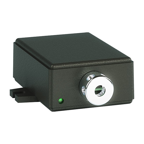
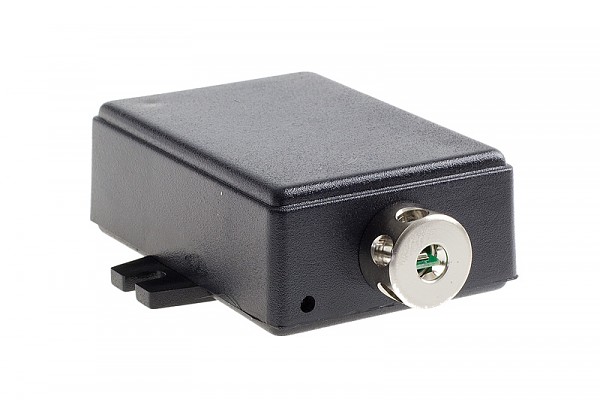
#08245Access sensor (Vutlan VT530)
The sensor made for checking whether the doors and windows have not been opened / closed.Installation Using patch-cable RJ-11 the sensor is connected to an analog input of any system unit. Determination of sensor's type and connection occur automatically. One of devices in the kit,
for example,
magnet,
is mounted on a door; the second device is mounted on a jamb of a door. At opening a door contact is disconnected,
and system of monitoring receives notification on opening. The first sensor is connected using patch-cable RJ-11 to an analog input of the system unit,
the consequent sensor is connected via patch-cable RJ-11 to an output of the first sensor and so on.Set includes Contact sensor,
magnet,
4-wired patch cable RJ-11 (2m),
two screws 4.8×16mm,
2 screws M5 and 2 nuts,
bracket,
double sided sticker.Max. distance 150m Net weight 106g Dimensions (LHW) Two compact devices with dimensions 60×18×18mm
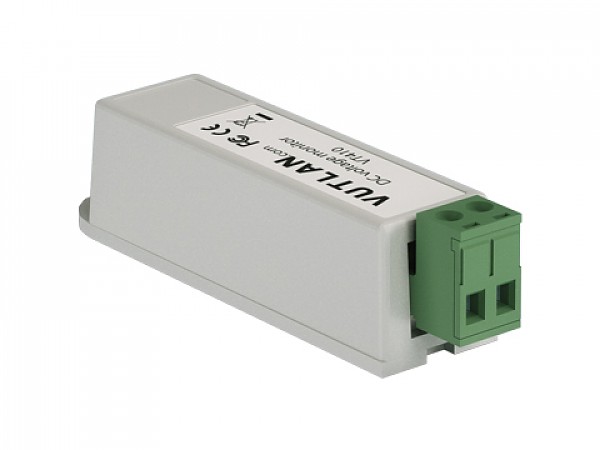
#08154DC voltage monitor (Vutlan VT410)
DC monitor is used for the measurement of DC voltage up to 75V and converting data into the format of the IP monitoring system. The system interface allows you to assign the sensor and to introduce the function data conversion.Voltage measured 0-75V Accuracy of measurement 1% Max. distance m 50m Net weight 100g Dimensions (LHW) 60×18×18 mm Only a 6P6C RJ12 cable can be used with the sensor! The cable is included with the sensor.
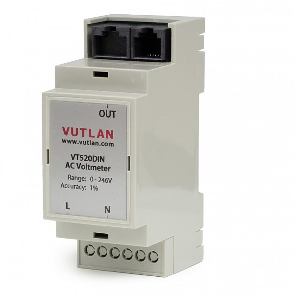
#03108DIN AC voltage monitor (Vutlan VT520DIN)
The sensor is used for the measurement of 0-246V, AC. It has a very high 1% accuracy. It can be used with any Vutlan monitoring system. DIN rail 35mm mounting.Voltage measured 0-246V AC Accuracy of measurement 1% Max. distance m 100m Net weight 125g Dimensions (HxWxD) 90.2×36.3×57.5mm
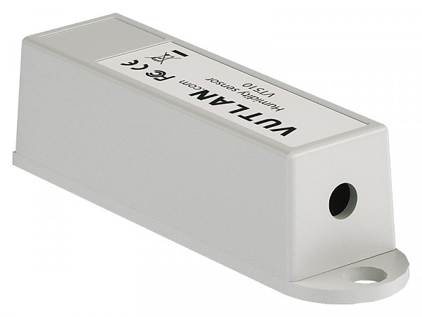
#08239Humidity sensor 5% (Vutlan VT510)
The sensor is made for measurement of relative humidity 10-95% indoors with a relative accuracy of 5%.Technical specifications Measured humidity range 10-95% RH Accuracy 5%RH Working temperature -10 .. +80°C Features Installation On the bottom there is a ledge with Ø4.5mm and height 1mm and a Ø5mm mounting hole fpr mounting the sensor. 5mm from it for fastening the sensor using 4.8×16 mm screw. Connection Humidity sensor contains RJ-11 jack and is connected to an analog input of any system unit. Determination of type of sensor and connection occur automatically. Supply includes Sensor,
4-wired patch cable RJ11 (2m),
4.8×16mm screw,
double sided sticker.Net weight 60g Dimensions 60×18×18mm Max distance 150m
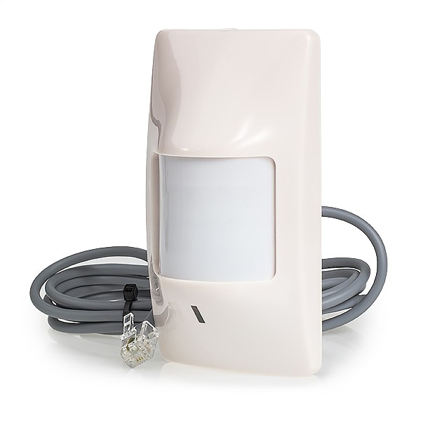
#08247Motion detector (Vutlan VT570)
Sensor made for movement detection via infra-red.Technical specifications PIR detection angle 110° Max. detection distance 50 m Features Installation On the bottom there is a mounting slot for fastening the sensor with a plastic bracket. Connection Motion sensor contains RJ-11 jack and is connected to an analog input of any system unit. Determination of sensor's type and connection occur automatically. To adjust sensitivity,
read manual. To change cable connection,
open the cover and read manual.Dimensions (LxHxW) 105×57×40mm Net weight 133g Supply includes Sensor,
cable RJ11 2m,
4.8×16mm screw,
2-pin terminal strip type TBW-5-2p,
double sided sticker.
#08243Outdoor temperature sensor (Vutlan VT501)
The sensor made for measurement of temperature outside of buildings, can also be used indoors.Technical specifications Operating temperature -50...+105°C Accuracy 3°C Max. distance 100m Features Installation An all-weather 2-pair UTP cable of 15m emerges from the cylinder. After installation of cylinder outside of a building,
the cable must be placed to reach the system unit.Connection After installation RJ-11 connector is connected to an analog input of any system unit. Determination of type of sensor and connection occur automatically. Supply includes 4-wired cable RJ11 (15m) with sensor head Net weight 340g Dimensions (LHW) Device has a shape of a Ø7×23mm cylinder
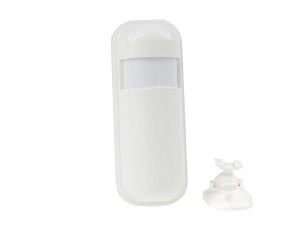
#03111Radar motion sensor (Vutlan VT572)
A microwave radar high-performance sensor is used for the detection of objects or human movement. This product is an indoor energy-saving high-sensitivity detector.
The scanned signal can penetrate plastic, glass, ceiling, wooden door, and thin walls.Technical specifications PIR detection angle 120° Sensing distance maximum is 12 meters Frequency Range 5.725GHz-5.875GHz Max. detection distance 100 m Features Installation On the bottom there is a mounting slot for fastening the sensor with a plastic bracket. Connection Motion sensor contains RJ-11 jack and is connected to an analog input of any system unit. Determination of sensor's type and connection occur automatically. To adjust sensitivity,
read manual. To change cable connection,
open the cover and read manual.Supply includes Sensor,
cable RJ11 2m,
holder
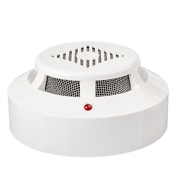
#08246Smoke sensor (Vutlan VT560)
The sensor monitors occurrence of smoke.Technical specifications Sensitivity 0,05 - 0,2 db/m Features Installation On the bottom there are Ø5mm mounting holes for fastening the smoke sensor to the surface by 4.8×20mm screws or/and bracket and M4 screws. Connection Detector's jack RJ-11 is connected to an analog input of any system unit using patch-cable RJ-11. Determination of the sensor's type and connection occur automatically. The monitoring system allows to connect several smoke detectors into a linear circuit. For this purpose each detector has two jacks RJ-11 input and output. The first is connected to an analog input of the system unit using a patch-cable RJ-11,
the consequent is connected via patch-cable RJ-11 to an output of the first detector and so on. as one sensor with one address.Supply includes Detector,
4-wired cable RJ11 (2m),
2 screws and 2 nuts M4,
2 screws 4.8×20mm,
bracket,
double sided sticker.Net weight 290g Dimensions (LHW) Ø100×45 Max distance 150m
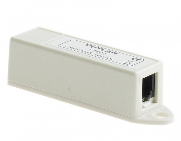
#03110Spot leak sensor (Vutlan VT593)
The sensor is used for level monitoring of conductive liquids in containers, pits, cellars, etc. Or it is used for leakage detection. The sensor has two stainless steel poles. The detector is encapsulated in plastic housing for conductive liquids. Can be placed near plumbing, trays, raised floors, under equipment, sinks, aquariums, sump pumps, refrigerators, dishwashers, toilets, basements, washing machines, water heaters, and garages.Technical specifications Temperature range -10… +80°C Max. distance 100 m Connection Connector RJ12 is connected to an analog input of any system unit. Determination of sensor's type and connection occur automatically. Set includes Sensor,
adapter,
4-wired cable RJ-12 (2m)Net weight 60g Dimensions (LHW) 60×18×18mm
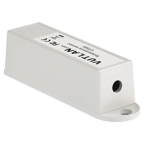
#08242Temperature sensor (Vutlan VT500)
The sensor is made for measurement of temperature indoors.
Measuring range: -10 ÷ 80°CTechnical specifications Operating temperature -10 ÷ 80°C Accuracy 1°C Features Installation On the bottom there is a ledge with Ø4.5mm and height 1mm and a Ø5mm mounting hole for fastening the sensor using a 4.8×16 mm screw. Connection Temperature sensor contains RJ-11 jack and is connected to an analog input of a system unit. Determination of type of sensor and connection occur automatically. Supply includes Sensor,
4-wired patch cable RJ11 (2m),
4.8×16mm screw,
double sided sticker.Net weight 50g Dimensions (LHW) 60×18×18mm Max distance 100m
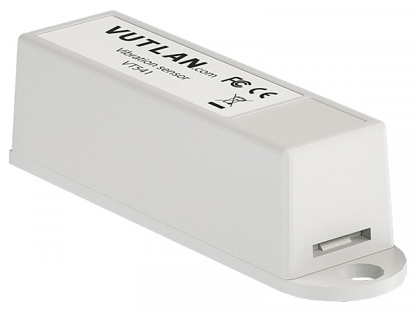
#08391Vibration detector (Vutlan VT540)
Sensor made for remote monitoring of vibration of the elements its attached to.
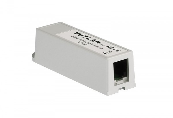
#08249Water detection cable sensor (Vutlan VT591)
The sensor informs about occurance of water or other liquids when it comes into contact with the WLC detection cable attached to the sensor.
The cable is placed under the raised floor, cabinets, air conditioners, etc.
The VT-WLC detection cable is necessary for the sensor.
The sensor is incompatible with the VT-WDC cable.Connection Can be connected via RJ-11 cable to each control unit. Determination of the sensor type and connection takes place automatically. At the end of the sensor,
connect the 2-wire VT-WLC detection cable.Maximum distance from the controller 100m The maximum length of the detection cable track 225m Set includes sensor,
cable,
terminal strip type TBW-5-2p,
screw 4.8×16mm,
double sided sticker,
VT-WLC adapterNet weight 60g Dimensions (LHW) 60×18×18mm
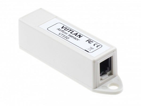
#08236Wind velocity meter (Vutlan VT550)
Sensor made for monitoring of air conditioners, fans, etc. Sensor controls airflow in the range of 0 - 3 m/s.Connection The sensor is connected to the controller by the RJ-11 network cable. Determination of the sensor type and connection takes place automatically. Sensor response time 0.1s Max. distance 50m Net weight 106g Dimensions 60×18×18mm Power Consumption 60mW Supply includes Sensor converter,
airflow sensor,
mounting bracket,
2m RJ11/RJ12 cable,
screws,
nuts,
bolts and a sticker.
- » CAN SENSORS#08295
Humidity and temperature sensor (Vutlanl VT490)
Digital sensor made for monitoring temperature and humidity inside buildings, rack cabinets, etc.Technical specifications Measured temperature range -40 ÷ 100°C Accuracy ±0.4°C in –10 to 85 °C range Measured humidity range 0 - 95%RH Accuracy %RH ± 3% RH in 0 to 80% range Maximum distance from the appliance 225m Features Connection Sensor's jack RJ-12 is connected to CAN input of any system unit or to a CAN output of another sensor using RJ-12 patch cable. Determination of sensor's type and connection occur automatically. The system enables connecting multiple sensors to a linear layout. For this purpose,
each sensor is equipped with two RJ-12 input and output sockets.Net weight 160g Dimensions 68 × 47 x 26 mm
#08145Pressure, humidity and temperature sensor (Vutlan VT450)
Digital sensor made for monitoring temperature, humidity and pressure.Communications Sesnor type CAN digital sensor Inputs/Outputs 2x RJ11 6p4c Daisy chain Yes,
a daisy chain is possible for all CAN sensors.Max. distance from the monitoring unit 225m LED indicators Red / Green (RUN/ERROR) Accuracy Pressure RMS noise 0.2Pa (equivalent to 1.7cm) Pressure error ±0.25% (equivalent to 1m at 400m height change) Pressure from °C ±1.5Pa/K (equivalent to ±12.6cm at 1 °C temperature change) RH accuracy ± 3% RH (max) Hysteresis ≤2% RH Response time 1s Temperature 1.5°C Environmental Pressure range 300 to 1100 hPa Working temperature range −40 to +85 °С Humidity operating range 0 to 95% RH Power Requirement Power input 12V DC,
1A (power supplied on a CAN bus chain)Current consumption 1 Watt Mechanics Dimensions 68x47x26 mm Packaging weight 160 g
#08237Smoke, humidity and temperature sensor (Vutlan VT460)
Digital sensor made for monitoring temperature and humidity and detecting smoke inside buildings, rack cabinets, etc.Technical specifications Smoke sensitivity 0,05 - 0,2 db/m Response time 10 sec Measured temperature range -10 to +75 °C Accuracy ±0.4°C in –10 to 85 °C range. Measured humidity range 0 - 95%. Accuracy %RH ± 3% RH in range of 0 - 80% Maximum distance from the appliance 225m Features Installation On the bottom there are mounting holes for fastening the smoke sensor to the surface using screws 4.8×20mm or/and bracket and M4 screws. Connection Sensor's jack RJ-12 is connected to CAN input of any system unit or to a CAN output of another sensor using RJ-11 patch cable. Determination of sensor's type and connection occur automatically. Monitoring system allows connection of up to 40 smoke sensors into a linear circuit. Set includes Sensor,
3-wired shielded patch cable RJ12 (2m),
bracket,
2 screws and 2 nuts M4,
2 screws 4.8×20mm,
double sided sticker.Net weight 310g Dimensions (LHW) Ø100×45mm
- » ADDITIONAL ACCESORIES#08117
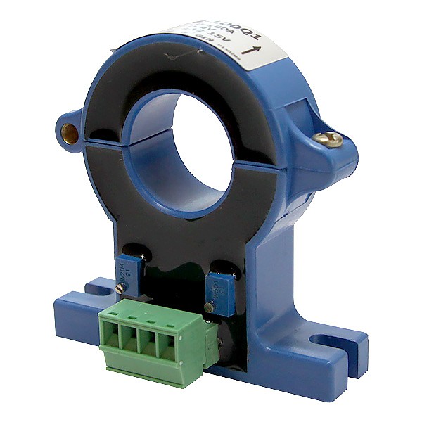
AC current transducer (Vutlan HAT-100Q1)
The clamp sensor enables the measurement of alternating current in the range of up to 100A. Itr can be used together with a VT407 converter (#08116).Connection: Power input -12V / +12V Outputs 4 pin terminal Power Consumption 1 Watt Operating temperature -10°C ÷ 80°C Operating humidity 5% ÷ 95%,
non-condensingNet weight 150g Dimensions (LHW) 68 × 47 x 26 mm / 60 × 61 × 16 mm #08116 HAT sensor transducer 0-5V DC (Vutlan VT407)
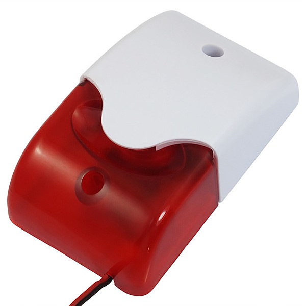
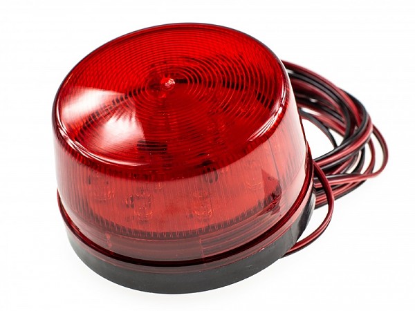
#08264Alarm beacon (Vutlan VT103)
The VT103 indoor optical-acoustic siren is dedicated to work with Vutlan environmental parameters monitoring units.Technical specifications Rated voltage 12V Sound pressure 108 dB Tone frequency 3.8 kHz Flash frequency 150 / min Net weight 140g Dimensions (LHW) 70 x 36 x 56 mm
#08344Alarm beacon (Vutlan VT105)
The 12V VT105 indoor optical-acoustic siren is dedicated to work with Vutlan environmental parameters monitoring units.Technical specifications Rated voltage 12V Flash frequency 90 / min Net weight 110g Dimensions (LHW) 73 x 45mm,
cable 3m
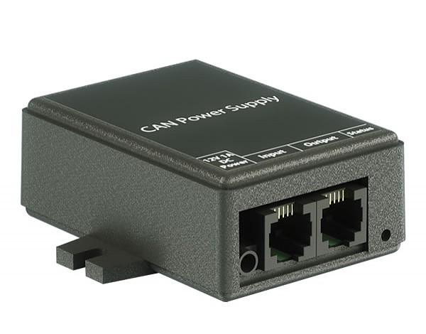
#03880CAN-12V-1A / CAN Power Supply Module
Increases the number of CAN sensors connected on a CAN bus chain. Supplies power for a maximum of 15 additional sensors. Needed only if the number of sensors in a CAN bus chain is greater than 12 sensors.Technical specifications Type Power supply for CAN bus chain Input RJ11 6P4C CAN port ⌀3.4/1,35 mm 12V Otuput RJ11 6P4C CAN port Daisy chain Allows daisy chain Max. q-ty of CAN sensors powered 15 LED indicators Green (Status On/Off) Environmental Working temperature range −40 °C to +100 °C Humidity operating range 0-95% RH Mechanics Dimensions 68 x 67 x 26,2 mm (LxWxH) Packaging weight 190g Mounting options Desktop,
Wall mount,
Indoor
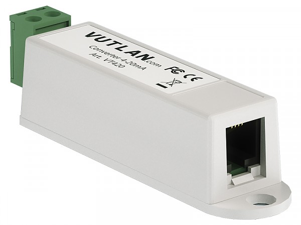
#08390Converter 4-20mA (Vutlan VT420)
Converter of current loop 4-20mA is used for measurement of constant current on 4-20mA outputs of sensors and converting data into a IP monitoring system format. The system interface allows you to assign the sensor and to introduce the function data conversion.
Galvanic isolation of 3 kV between I/O is used in a receiver.
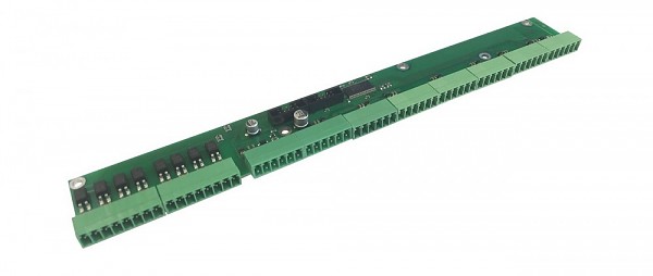
#08186Dry contacts board IN/OUT (Vutlan VTX40)
A complementary module for VT900 and VT960 DC master units.Technical specifications Dry contacts x32 dry contact inputs,
x8 isolated dry contact outputsConnection BH-10 Supply includes BH-10 bus cable,
x8 terminals (6P 3.5mm),
x2 terminals (8P 3.5mm),
x5 screwsDimensions (LHW) 241 x 35 x 11 mm
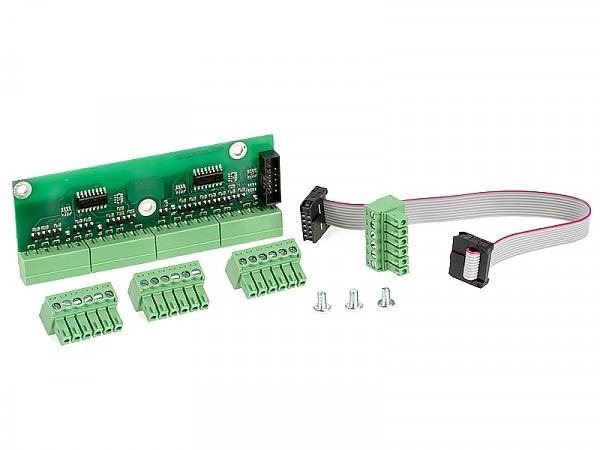
#08235Dry contacts module (Vutlan VT16)
Complementary module for moin units, can be connected to 16 dry contacts.
Dedicated for SC8100, VT8101, VT8110, VT800.Technical specifications Dry contacts 16 Contact outputs 3.5 mm Features Installation On the PCB there are 3 mounting holes for fastening to the surface using screws 3 mm inside of any master unit. Connection Jack IDC2-10 is connected to IDC2-10 input of master unit. Determination of PCB's type and connection occur automatically. Monitoring system allows connection of up to 16 dry contacts. Supply includes PCB,
10-wired IDC2 cable (10cm),
3 screws M3.Net weight 80g Dimensions (LHW) 70x10×25mm
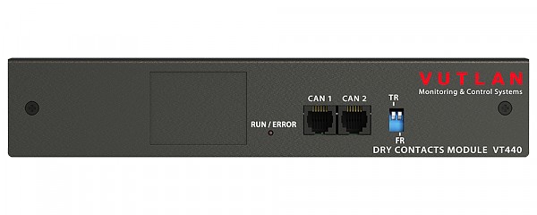
#08916Dry contacts unit (Vutlan VT440)
Allows to increase the number of dry contacts connected to any Vutlan monitoring unit. Adds 32 dry contacts (or 64 with VT32 module). Can be connected to any CAN port.Number of dry contacts 32 - 64 Contact outputs 3.5mm Max contact distance 500m Number of CAN ports 2 (1 input,
1 output)Mounting The unit includes two 19" mounting angles for mounting inside the rack. Alternatively,
there are 2 mounting holes on the bottom of the case for fastening on the wall. Fasten the unit,
connect CAN inputs to the input of the previous CAN unit or of the monitoring unit. The red LED lights up. Match the bus terminators of the CAN units. Switch terminator TR in ON position on the monitoring unit and on the last CAN unit,
TR on intermediate CAN units are in Off (1,2) position. Maximum 8 CAN units,
sensors and/or devices can be on one CAN bus.Inventory Unit,
3-pair shielded patch cable RJ-12 2 m length,
screw 3.5 x 16 mm,
fastener 2-sided,
rubber feet,
19" mounting angles.Net weight 0.5 kg Dimensions (LHW) 215×40×40mm
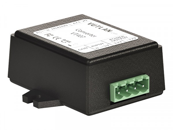
#08116HAT sensor transducer 0-5V DC (Vutlan VT407)
The transducer is used together with HAT-100Q1 current transducer.Power input 12V DC,
1AInput RJ-12 / RJ-11 Power Consumption 100mW Operating temperature -10°C ÷ 80°C Operating humidity 5% ÷ 95%,
non-condensingNet weight 150g Dimensions (LHW) 68 × 47 x 26 mm Max distance 50m #08117 AC current transducer Vutlan HAT-100Q1
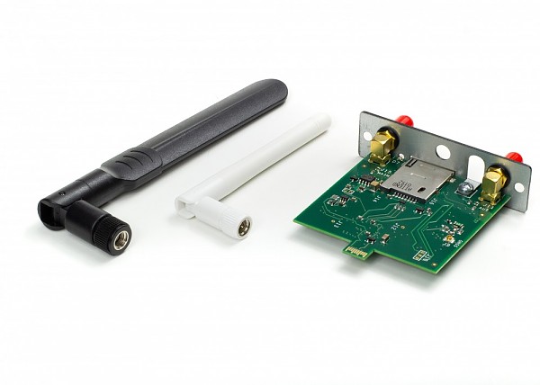
#08197Internal LTE, GPS modem (Vutlan VT710)
A modem for Vutlan monitoring units (VT900, VT900 DC, VT960, VT960 DC). The module enables sending SMS about the system status / alarms and access to the Internet via LTE network. Antennas are not included with the module, must be purchased separately. The GPS function is used to synchronize the time according to geographic location.Antennas:
#08354 GPS Antenna 3 dBi 3m(Vutlan VT6691)
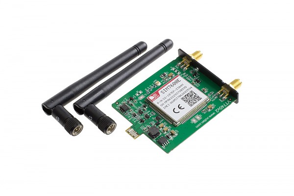
#03105Internal LTE, GPS modem (Vutlan VT740)
4G LTE slot modem for Vutlan monitoring units. Allows to receive and send SMS messages. Provides Ethernet over 4G LTE. Power-cycling is an embedded function.
Can be used together with VT335t, VT825t/VT825tt, VT855t/VT855tt & VT604/VT608.
Antennas included.
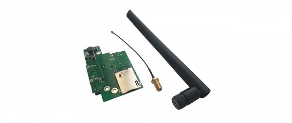
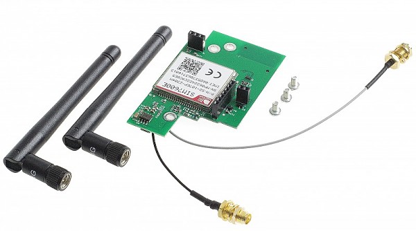
#08318Internal LTE, GPS modem (Vutlan VT760)
A modem for Vutlan monitoring units VT335S, VT335S DC, VT805, VT825, VT604. The module enables sending SMS about the system status / alarms and access to the Internet via LTE network. The GPS function is used to synchronize the time according to geographic location. Antenas inculded.INTERFACE Network interface WCDMA/HSDPA/HSPA+ B1/B5/B8 LEDs Red / Green Led Chip SimCom Extension protocols FDD-LTE B1/B3/B5/B7/B8/B20 Uplink up to 5Mbps Downlink up to 10Mbps Dimensions (LxHxW) 60 x 50 x 15 mm Net weight 60 g Installation There are 3 mounting M3 holes on a board.
#03099Internal LTE, GPS modem (Vutlan VT790)
4G LTE slot modem for Vutlan monitoring units. Allows to receive and send SMS messages. Provides Ethernet over 4G LTE. Power-cycling is an embedded function.
Can be used together with VT960i & VT960ii.
Antennas included.
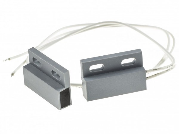
#08370Magnet access sensor (Vutlan KMS-30)
The sensor made for checking whether the doors or windows have been opened/closed.Installation Insert the terminal into "Dry contact Input" of Vutlan monitoring system. Supply includes magnet sensor,
4x screws M3 12.5mm,
2x stickers.Max. distance 500m Power consumption 6W Dimensions (WHL) Two 60x18x18mm compact devices
#03120Modbus RTU Slot Extension (Vutlan VT485m)
Allows to monitor up to 32 Modbus RTU devices/meters/sensors. The maximum distance of a daisy chain is up to 1000 meters. Each metered value of a Modbus device is addressed individually using input registers and is shown by the system as virtual sensors. You can configure thresholds and icon representations for these elements.
It can be used with VT335t, VT336t, VT825t, and VT855t monitoring systems. A slot PCB board can be inserted inside the monitoring unit while the unit is in operation. Has an internal termination and by default, it is switched ON (if required can be turned off).
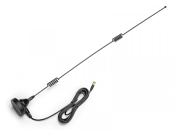
#08368Omni-directional GSM antenna 7 dBi (Vutlan VT6604)
Omnidirectional gain 7 dBi Frequency range 890-960 / 1710-1890 / 1920-2170 MHz Impedance 50 Ω Connector SMA(M) Cable RG174 Mounting Possibilities Has A Magnet At The Bottom Cable lenght 3m Temprature Min. -10° C - Max.80° C Size ∅50 x 520 mm Manufacturer Vutlan
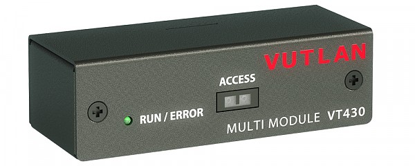
#08917Rack control unit (Vutlan VT430)
The module has a PIR sensor for rack door control, 2 dry contacts and a humidity sensor. Connected to a CAN port, it allows further CAN chain connection.
Sensors and contacts appears in the system automatically.
Max. distance from the monitoring unit is 300 meters.Technical specifications Measured humidity range 10-95% RH Accuracy 5% RH PIR sensor disrance 30mm Number of dry contacts 2 Number of CAN ports 2 Maximum distance from the appliance 300m Features Installation There are 4 mounting holes on the bottom of the case for fastening. Fasten the unit,
connect CAN inputs to the input of the previous CAN unit or of the monitoring unit.Connection Sensor's jack RJ-12 is connected to CAN input of any system unit or to a CAN output of another sensor using RJ-12 patch cable. Determination of sensor's type and connection occur automatically. Supply includes Unit,
shielded patch cable RJ-12, 2 screws and 2 nuts M6,
sticker,
dry contacts connector..Net weight 0.2 kg Dimensions (LHW) 89×27×36mm
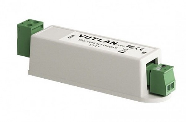
#03107Relay contact 5A (Vutlan VT11)
Relay switchable contact. Can be used together with equipment, for example for switching ON/OFF air conditioners. Can control power for magnetic locks, bolt locks, solenoid electromagnets, siren, light source, heater and etc.
Can be connected to any monitoring system or device with 12V outputs.Technical specifications Max. switching voltage 250VAC / 30VDC Max switching current 5A Max. switching power 1250VA / 150W Min. contact load No gold plated,
5VDC 10mAFeatures Max distance 200m Power Consumption 12mW Net weight 60g Dimensions (LHW) 60×18×18mm Operating temperature Min. -50° C - Max.+105° C Package includes x2 wire cable (1 meter),
screw M5 L15mm,
x1 3.81mm 2P terminal,
x1 5.0 2P terminal,
sticker
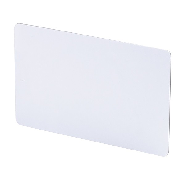
#08297RFID Card (Vutlan VT108)
Unique proximity cards for VT107 card readers.Technical specifications Rated voltage 12V Memory 64bit Frequency 125 kHz Standard EM4100 Net weight 7g Dimensions (LHW) 86 x 59 x 1 mm Accessories:
#08269 RFID Card reader (Vutlan VT107)
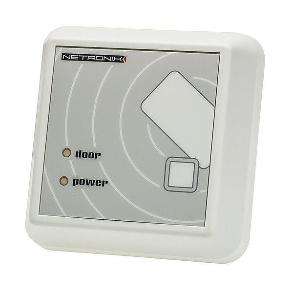
#08269RFID Card reader (Vutlan VT107)
Proximity card reader for contactless reading data from RFID cards (Unique standard). Dedicated for VT855i/VT855ii & VT960i/VT960ii.Technical specifications Rated voltage 12V Current 30 - 55 mA Frequency 125 kHz Range response 15 cm Net weight 100g Dimensions (LHW) 82 x 82 x 22 mm #08297 RFID Card (Vutlan VT108)
#03126
SE Mini Reader
Versatile miniature reader for proximity identifiers. Highly secure, open technology OSDPv2 reader. Resistant against moisture, dust, and vandal-proof. Easy to configure. Works with Mifare Plus cards in SL3 security mode.
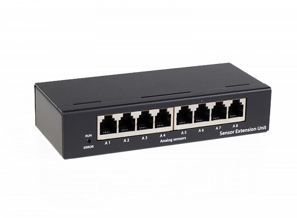
#08288Sensor unit (Vutlan VT408)
Module allows to increase the number of sensors connected to the Vutlan master module. The expansion unit is connected to the CAN connector of the controller.Number of analog ports 8 Number of CAN ports 2 Maximum bus length 300 meters Maximum analog sensor cable length 50-150 meters,
depending on the sensor typeInstallation In the lower part of the casing there are Ø 5 mm holes for mounting the module, at a distance of 50 mm and 89 mm from the center. The cable is connected to the connector on the side wall. Connection Can be connected via RJ-12 cable to the CAN input of the control unit or another CAN sensor. The module is automatically detected on the first connection. Set includes module,
CAN cable RJ-12 (2m),
3.5x16mm screwsNet weight 0.6 kg Dimensions (LHW) 110×68×40 mm
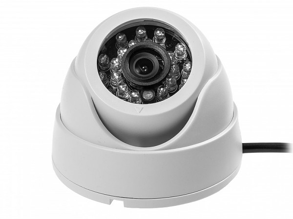
#08204USB100 / USB dome camera
USB UVC/MJPEG digital camera with high resolution and with IR Leds for direct connection to the VUTLAN system controller.
It allows to view the monitored room on an ongoing basis as well as send a video sequence to an email address in response to a defined event.
In addition, the camera connected to the VUTLAN controller is visible in the network at a dedicated URL, allowing to capture the video stream just like from an IP camera (MJPEG stream).HARDWARE FEATURES: Interface USB format(Complies with USB 2.0 CAMERA: Image Sensor 1/4" Color CMOS H62 Resolution 1.0 Megapixel (640 x 480) Minimum Illumination 0.01 Lux @ F1.2 VIDEO/IMAGE: Video Compression MJPEG Frame Rate & Resolutions Max. 20 fps at 640x480 (VGA),
Max. 20 fps at 320x240 (QVGA)Video Streaming Controllable Frame Rate OTHERS: Cable lenght 2,6m Operating Temperature 0°C∼ 40°C (Humidity 0% RH∼ 80% RH) Weight 550g
#03128
VT-BAT / Reservation battery 9V
"VT-BAT / Reservation battery 9V" keeps the device operational while the main power source is disabled. The device uses a non-rechargeable 6F22 9V lithium battery. The Vutlan monitoring system may work from this battery for approximately 1 to 10 hours.
A 9V is not included. You can use a 9V battery enclosed in a standard PP3 enclosure.
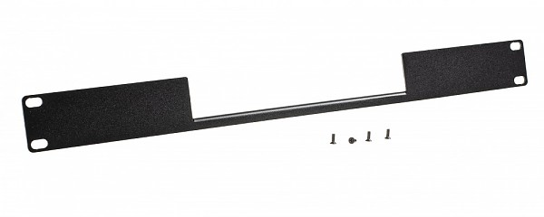
#03106VT122i / 19" holder (for VT335t)
Holder / bracket for VT335t monitoring unit #03113 (and older VT355i) . 1U rack mount, 19".
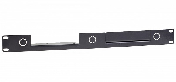
#03114VT122t / 19" holder (for VT335t + VT408)
Holder / bracket for VT335t monitoring unit #03113 and sensor extension unit VT408 #08288. 1U rack mount, 19".
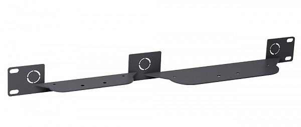
#03119VT125t / 19" holder (for 2x VT408)
Holder / bracket for x2 pcs of VT408 / Sensor extension units. 1U rack mount, 19".
#03121VT485r / OSDPv2 Reader Extension
Allows to connect readers, and keypads with OSDP protocol support. It is an extension PCB board and should be purchased separately.
It can be used with VT335t, VT825t, and VT855t monitoring systems. VT485r can be inserted inside the monitoring unit while the unit is in operation. VT485r has internal termination and by default, it is switched ON (if required can be turned Off).
Allows to connect SE mini reader, SE keypad, and any other 3rd party OSDP readers or keypads.
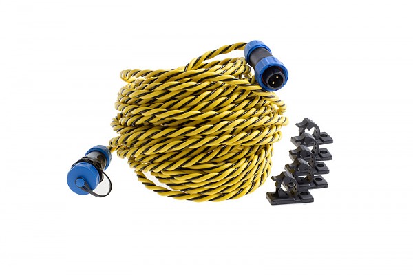
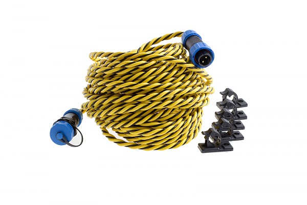
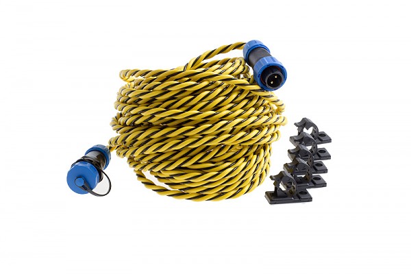
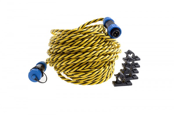
#03092Water leak cable (Vutlan VT-WLC10)
10m long detection cable for use with the # 08249 flood sensor. Unlike the WDC cable, the WLC cable can be used in rooms with very high humidity, pollution or hazardous waste.
Detectable liquids: clean, polluted and distilled water; acids; alkalis; alcohols and other electrically conductive liquid.Product code VT-WLC10 Lenght 10m Max operational lenght 225m Manufacturer Vutlan
#03093Water leak cable (Vutlan VT-WLC15)
15m long detection cable for use with the # 08249 flood sensor. Unlike the WDC cable, the WLC cable can be used in rooms with very high humidity, pollution or hazardous waste.
Detectable liquids: clean, polluted and distilled water; acids; alkalis; alcohols and other electrically conductive liquid.Product code VT-WLC15 Lenght 15m Max operational lenght 225m Manufacturer Vutlan
#03094Water leak cable (Vutlan VT-WLC25)
25m long detection cable for use with the # 08249 flood sensor. Unlike the WDC cable, the WLC cable can be used in rooms with very high humidity, pollution or hazardous waste.
Detectable liquids: clean, polluted and distilled water; acids; alkalis; alcohols and other electrically conductive liquid.Product code VT-WLC25 Lenght 25m Max operational lenght 225m Manufacturer Vutlan
#03124
Water leak cable (Vutlan VT-WLC3)
3m long detection cable for use with the # 08249 flood sensor. Unlike the WDC cable, the WLC cable can be used in rooms with very high humidity, pollution or hazardous waste.
Detectable liquids: clean, polluted and distilled water; acids; alkalis; alcohols and other electrically conductive liquid.Product code VT-WLC3 Lenght 3m Max operational lenght 225m Manufacturer Vutlan
#03095Water leak cable (Vutlan VT-WLC50)
50m long detection cable for use with the # 08249 flood sensor. Unlike the WDC cable, the WLC cable can be used in rooms with very high humidity, pollution or hazardous waste.
Detectable liquids: clean, polluted and distilled water; acids; alkalis; alcohols and other electrically conductive liquid.Product code VT-WLC50 Lenght 50m Max operational lenght 225m Manufacturer Vutlan
#03125
Water leak cable (Vutlan VT-WLC6)
6m long detection cable for use with the # 08249 flood sensor. Unlike the WDC cable, the WLC cable can be used in rooms with very high humidity, pollution or hazardous waste.
Detectable liquids: clean, polluted and distilled water; acids; alkalis; alcohols and other electrically conductive liquid.Product code VT-WLC3 Lenght 6m Max operational lenght 225m Manufacturer Vutlan
-

.jpg)





















.jpg?1639485830)







































.jpg?1659442143)


