
 MENU
MENUPRICE REDUCTIONS


- Computer Network Accessories
-
- » MAIN UNITS#03118
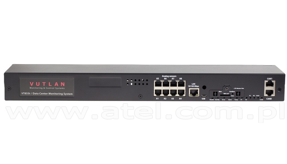
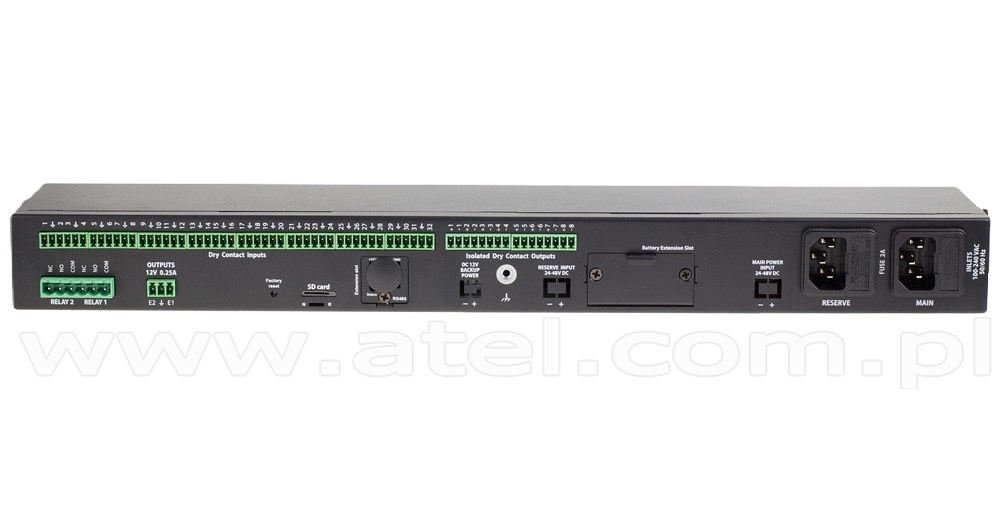
Monitoring unit 19" 1U; 8x analog; 2x CAN; 32x dry contact inputs (Vutlan VT855tt)
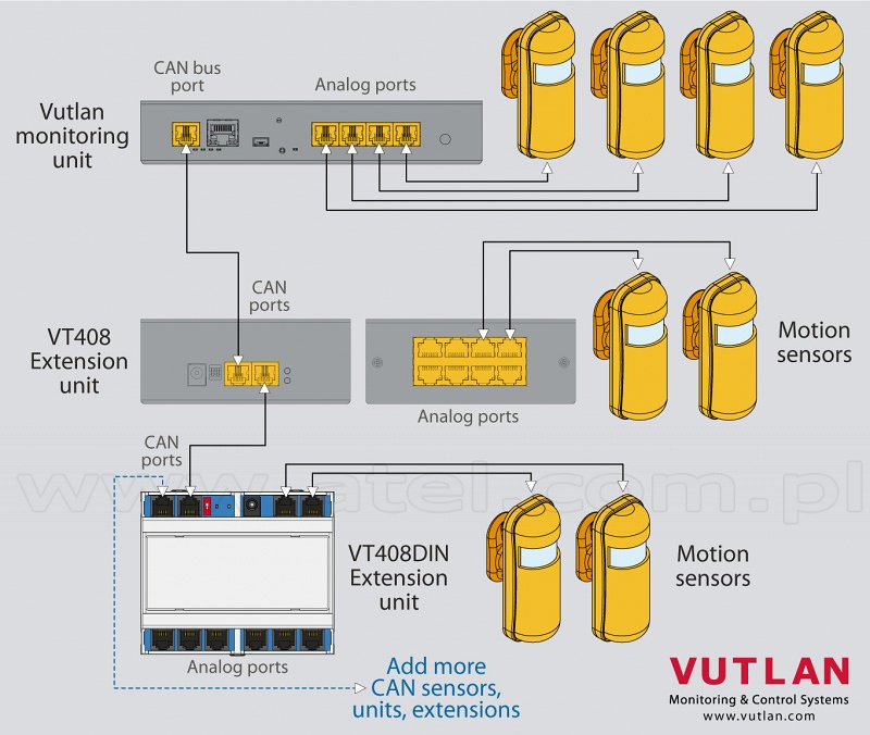
VT855tt / Data Center Monitoring System is used for environmental monitoring (e.g. temperature, humidity, voltage, leakage, smoke, airflow). It is also used as an I/O controller (e.g. door control, fans, generator, control panels, UPS, circuit breakers, and alarms). Can use up to 1000 different elements - notifications, triggers, timers, logic schemes, sensors, dry contacts. Has a built-in Web interface with virtual sensors, logic schemes, different types of notifications, and control panels.
Order options:
1 power inlet (VT855t) or 2 power inlets (VT855tt), providing a redundant power supply for A&B power distribution.REMOTE CONTROL IP monitoring Web,
SNMP,
SMS (LTE modem art. VT7670 is ordered separately!)Sensors control Administrative 3-level control of sensors using login INTERFACE & PROTOCOL SUPPORT Interface Access via any Internet browser. LAN Ethernet 10/100Mbit Network protocols DHCP; HTTP; HTTPS; DynDNS; SSL; SNMP v1,
v2c,
v3; SMTP; FTP; Syslog; RADIUS; OpenVPN; TLS (v1.0,
v1.1,
v1.2,
v1.3)OS Linux 6.2 Processor Cortex A7 1GHz Total CPU cores 2 RAM 128MB Software Built-in software for events processing. Alert type FTP,
syslog,
SMTP or SNMP,
SMS (LTE modem #03133 is ordered separately)A maximum number of "mail to" recipients 20 A maximum number of "SMS to" recipients in an SMS notification 20 Pings Built-in ping LEDs CAN,
ACT,
E1,
E2,
Error,
Relays R1 and R2Clock Built-in clock with time synchronization Watchdog Built-in watchdog timer The maximum amount of sensors 150 The maximum amount of elements 1000 USB cameras x1 IP cameras x4 POWER Power req 2x IEC C14 90-240V 1A fuse or 2x DC (24V/48V) or 1x AC + 1x DC Power consumption 10W Power reservation 12V,
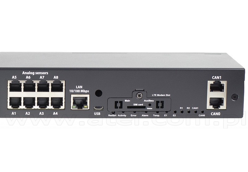
built-in voltage monitorINLETS/OUTLETS Ethernet 100Mbit USB USB 2.0 Typ C Analog port 8x6P4C for connecting any analog sensor. CAN BUS 2 x 6P6C for connecting up to 32 CAN sensors (over 12 sensors,
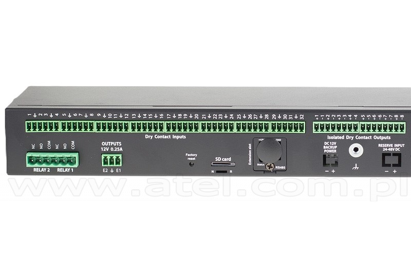
regeneration of the signal is required using the CAN # 03880 power module). Fuse protection on each line.Relay outputs 2 ports Alarm relay 2 x 12V 0.25A alarm port for VT103 Alarm Beacon (#08264) or VT105 (#08344) Dry contact inputs 32 x dry contacts input + 8 x dry contacts output EXTERNAL MEMORY Micro SD card Micro SD card slot (SDXC up to 512 Gb - saving logs,
record video,
run software,
databases and scripts)FEATURES Installation 19" cabinet or desktop Dimensions (WxHxD) 440mm × 44mm × 90mm Net weight 1.5 kg Working temperature Min. -10° C - Max. 80° C Supply includes Monitoring unit,
power cable 240V,
RJ45 cord,
manual,
warranty,
4 self-adhesive rubber legs,
plugs,
19" mounting angles.Warranty 3 years
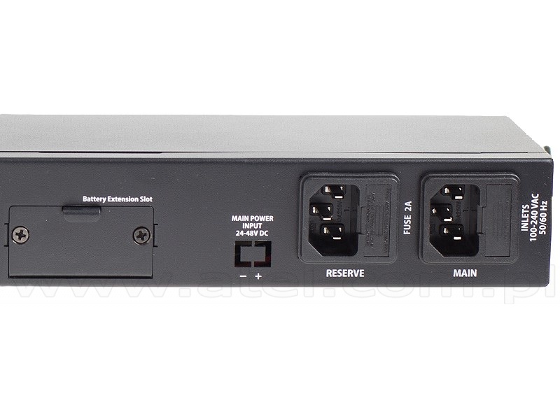
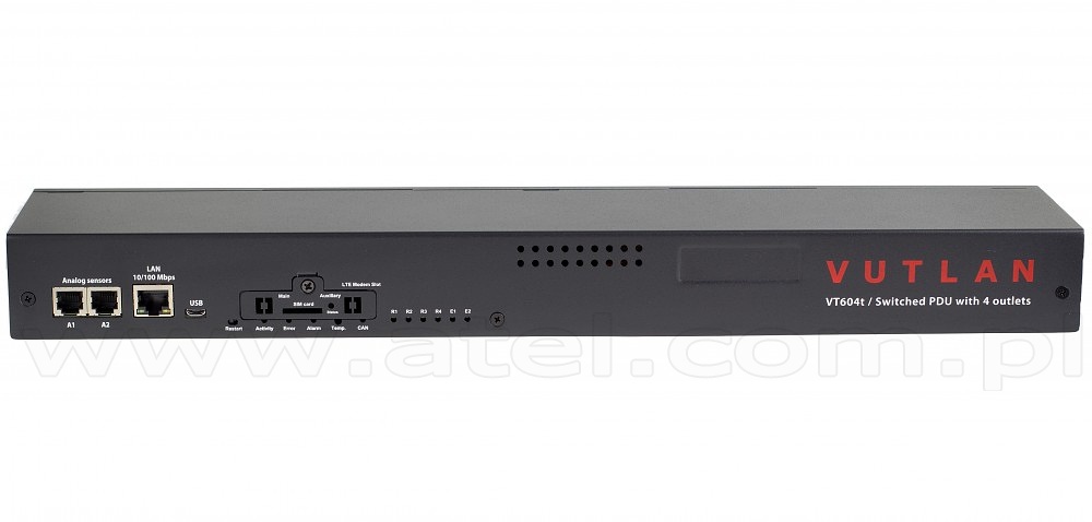
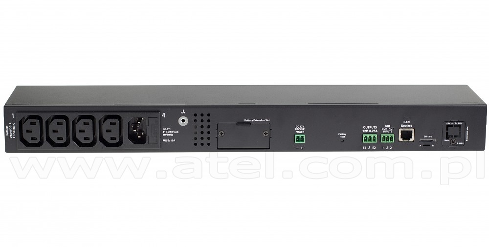
#03122Power distribution unit 2x analog, 1xCAN, 4x 230V (Vutlan VT604t)
The control unit supports 4 controlled 230V power sockets, 2 analog sensors, 2 potential-free sockets, 2 12V sockets and a LTE modem.
It allows remote switching on/off or restart for up to 4 connected devices.REMOTE CONTROL IP monitoring Web,
SNMP,
manual SMS (GSM modem art. VT740 #03133 is ordered separately!)Sensors control Administrative 3-level control of sensors using login INTERFACE & PROTOCOL SUPPORT Interface Access via any Internet browser. LAN Ethernet 10/100Mbit Network protocols HTTP; HTTPS; DynDNS; SSL; SNMP v1,
v2c,
v3; SMTP; FTP; Syslog; RADIUS; OpenVPNOS Linux 6.2 Processor dual-core CortexTM-A7 720 MHz / 128 MB Software Built-in software for events processing. Alert type FTP,
syslog,
SMTP or SNMP,
SMS (LTE modem art. VT7670 #03133 is ordered separately!)Pings Built-in ping LEDs STATUS,
E1,
E2,
ERR,
4x OUTLETClock Built-in clock with time synchronization Watchdog Built-in watchdog timer POWER Power input IEC C13 240V x 16A. Fuse protection. Power output 4x C13 240V Power consumption 10W INPUTS/OUTPUTS Ethernet 100Mbit Mini USB AB USB 2.0 HS Analog port 2x 6P4C for connection of any analog sensor. CAN BUS 1 x 6P6C for connection of up to 32 CAN sensors on each BUS. Relay outputs 4x C13 230V/10A power sockets Built-in sensors Temperature sensor (1%),
Power supply voltage sensor (1%)Dry contacts input x2 12V outlets 2x 0.25A EXTERNAL MEMORY Micro SD card Micro SD card slot (SDXC up to 512 Gb - saving logs,
record video,
run software,
databases and scripts)FEATURES Installation 19" cabinet Dimensions (LxHxW) 440 x 44.45 (1U) x 79 mm Operating characteristics Humidity - Min. 5% - Max. 95% (Non-Condensing),
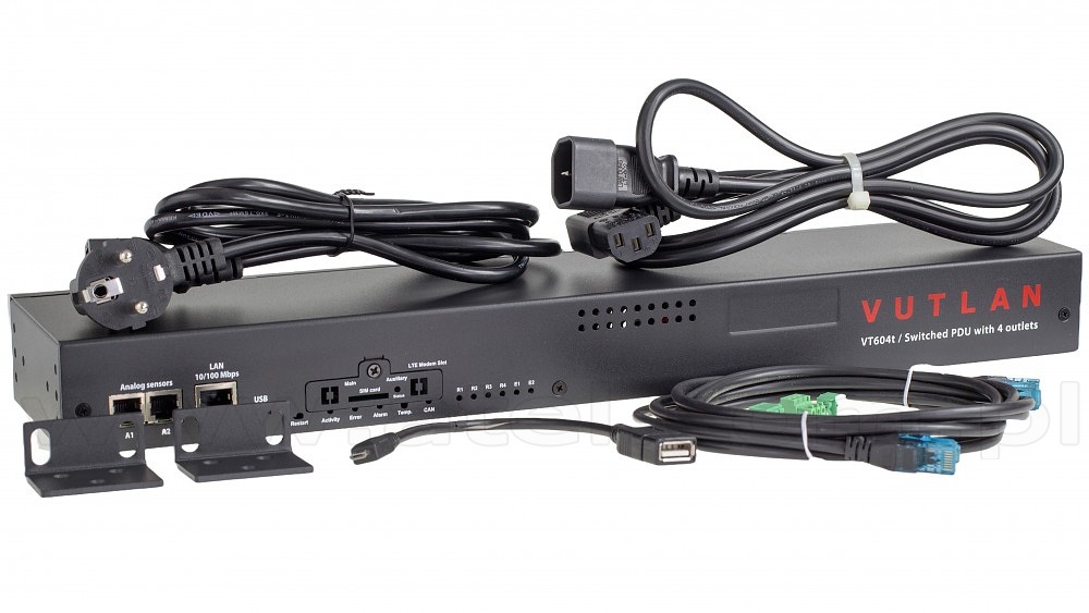
Temperature - Min. -10° C - Max.80° CNet weight 1,5 kg Supply includes EU Schuko C12 0.75 мм2 230V 10A cable,
IEC C13 Socket to IEC C14 Plug Power Cord,
Self-adhesive rubber foot 4 pcs,
Warranty card,
Short description and connection guide,
Patch cable RJ-45 1m,
Terminal plug 3 pins 3.5mm 1pcs,
Terminal plug 3 pins 3.81mm 1pcs,
Terminal plug 2 pins 3.81mm 1pc,
19" mounting brackets 2pcs,
Screws 6pcs M3 8mmWarranty 3 years Chosen accessories:
#03133 Internal LTE, GPS modem (Vutlan VT7670)
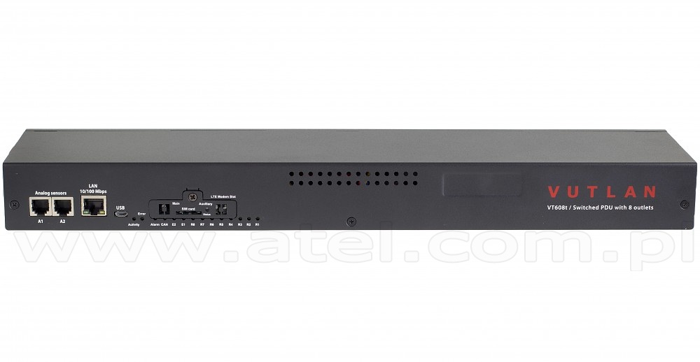
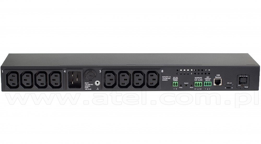
#03123Power distribution unit 2x analog, 1xCAN, 8x 230V (Vutlan VT608t)
The control unit supports 8 controlled 230V power sockets, 2 analog sensors, 2 potential-free sockets, 2 12V sockets and a LTE modem.
It allows remote switching on/off or restart for up to 8 connected devices.REMOTE CONTROL IP monitoring Web,
SNMP,
manual SMS (GSM modem art. VT7670 #03133 is ordered separately!)Sensors control Administrative 3-level control of sensors using login INTERFACE & PROTOCOL SUPPORT Interface Access via any Internet browser. LAN Ethernet 10/100Mbit Network protocols HTTP; HTTPS; DynDNS; SSL; SNMP v1,
v2c,
v3; SMTP; FTP; Syslog; RADIUS; OpenVPNOS Linux 6.2 Processor dual-core CortexTM-A7 720 MHz / 128 MB Software Built-in software for events processing. Alert type FTP,
syslog,
SMTP or SNMP,
SMS (LTE modem art. VT7670 #03133 is ordered separately!)Pings Built-in ping LEDs STATUS,
E1,
E2,
ERR,
4x OUTLETClock Built-in clock with time synchronization Watchdog Built-in watchdog timer POWER Power input IEC C20 240V x 16A. Fuse protection. Power output 8x C13 240V Power consumption 10W INPUTS/OUTPUTS Ethernet 100Mbit Mini USB AB USB 2.0 HS Analog port 2x 6P4C for connection of any analog sensor. CAN BUS 1 x 6P6C for connection of up to 32 CAN sensors on each BUS. Relay outputs 8x C13 230V/10A power sockets Built-in sensors Temperature sensor (1%),
Power supply voltage sensor (1%)Dry contacts input x2 12V outlets 2x 0.25A EXTERNAL MEMORY Micro SD card Micro SD card slot (SDXC up to 512 Gb - saving logs,
record video,
run software,
databases and scripts)FEATURES Installation 19" cabinet Dimensions (LxHxW) 440 x 44.45 (1U) x 79 mm Operating characteristics Humidity - Min. 5% - Max. 95% (Non-Condensing),
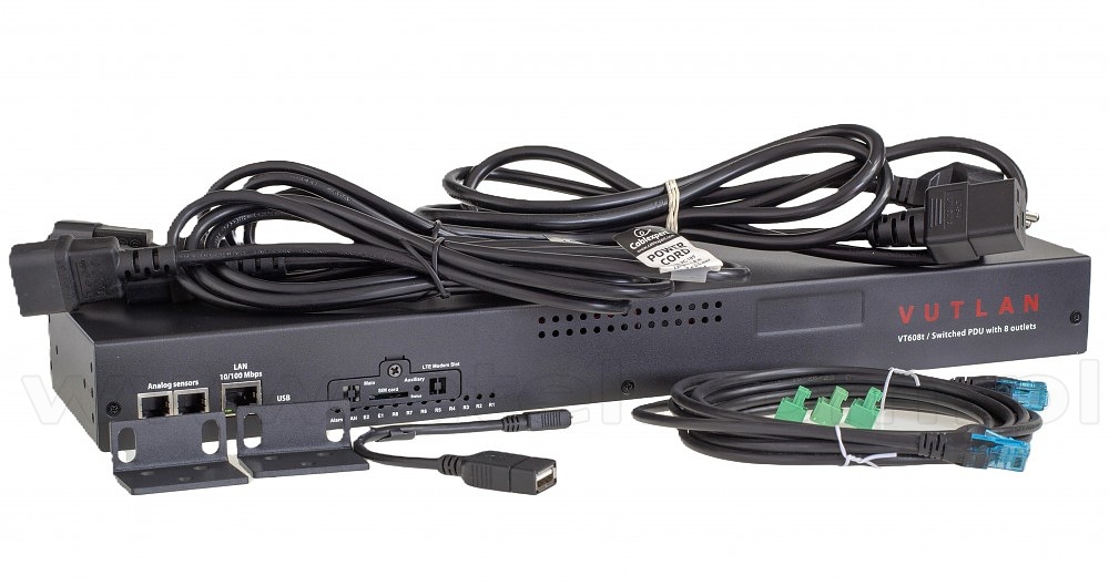
Temperature - Min. -10° C - Max.80° CNet weight 1,5 kg Supply includes EU Schuko C20 0.75 мм2 230V 10A cable,
2x IEC C13 Socket to IEC C14 Plug Power Cord,
Self-adhesive rubber foot 4 pcs,
Warranty card,
Short description and connection guide,
Patch cable RJ-45 1m,
Terminal plug 3 pins 3.5mm 1pcs,
Terminal plug 3 pins 3.81mm 1pcs,
Terminal plug 2 pins 3.81mm 1pc,
19" mounting brackets 2pcs,
Screws 6pcs M3 8mmWarranty 3 years Chosen accessories:
#03133 Internal LTE, GPS modem (Vutlan VT7670)
- » ANALOG SENSORS#08244
AC voltage monitor (Vutlan VT520)
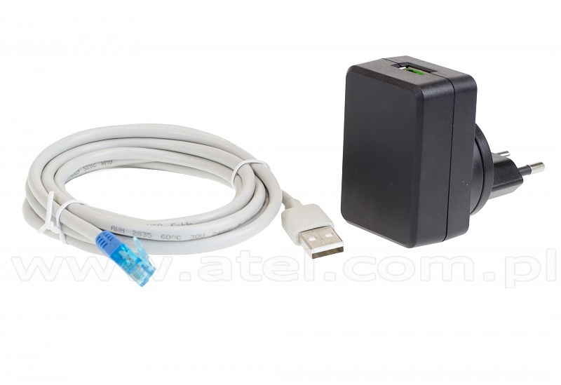
The sensor is made for measurement of 220-230V standard power supply or any other power sources in e.g. an outlet, on an extension cord or in a rack-mountable socket strip.Connection Plug 220V is put into the outlet necessary for measurement of 220V. Cable's USB connector must be connected to the USB output,
connector RJ-11 must be connected to an analog input of any system unit. Determination of sensor's type and connection occur automatically.Set includes Sensor and USB RJ-11 patch cable (1.8 m). Voltage measured 90-250V Accuracy of measurement 2% Max. distance m 100m Net weight 125g Dimensions (LHW) 63×66×40mm
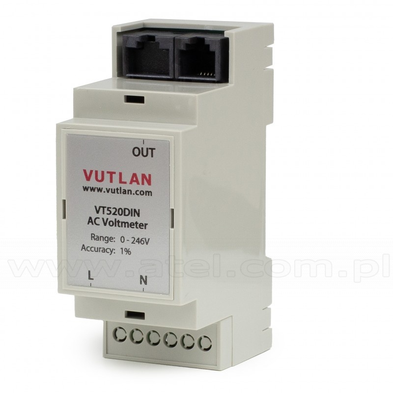
#03108DIN AC voltage monitor (Vutlan VT520DIN)
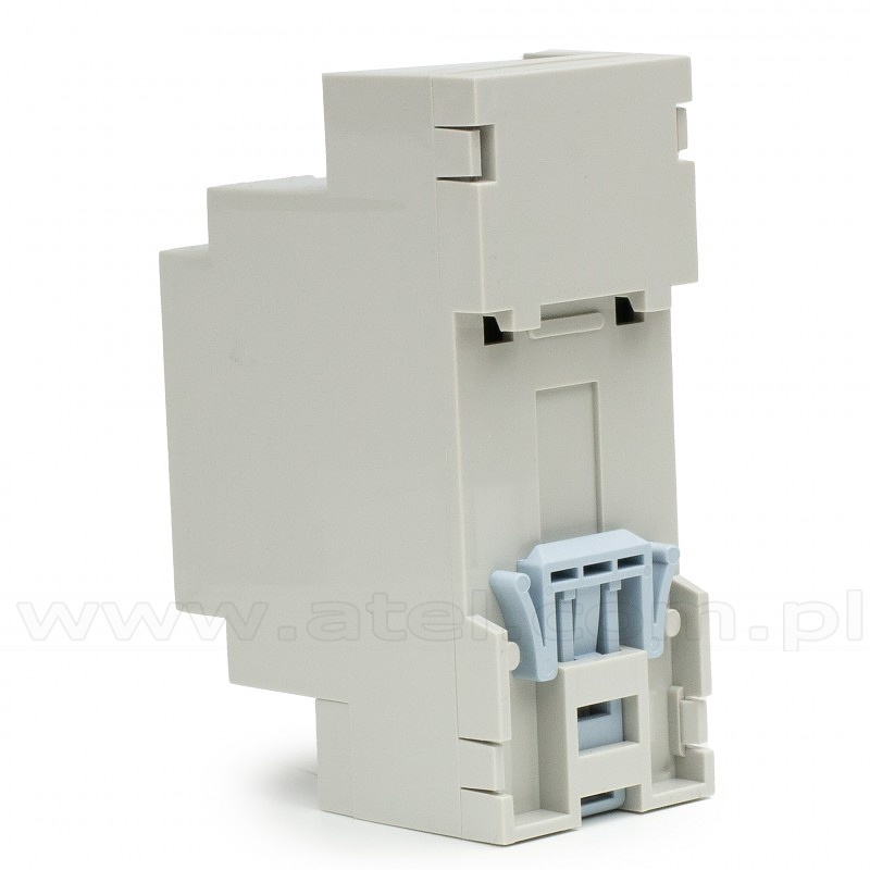
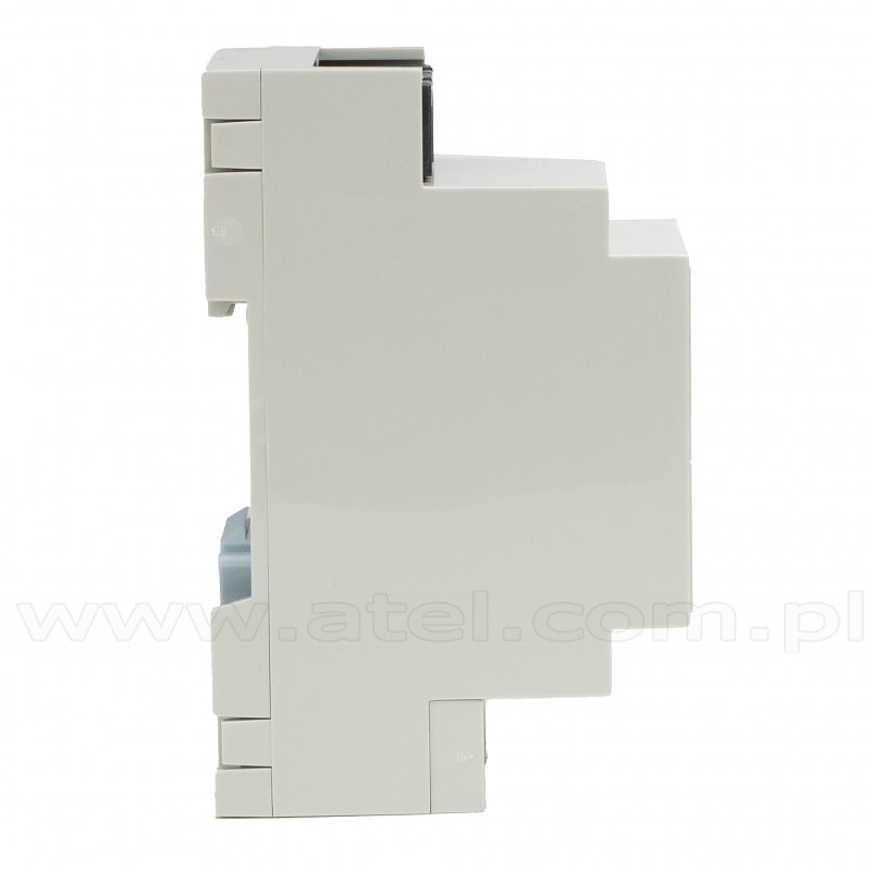
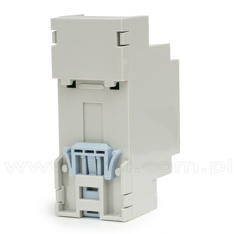
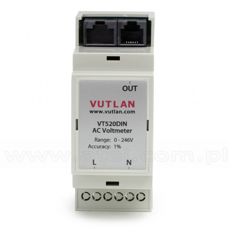
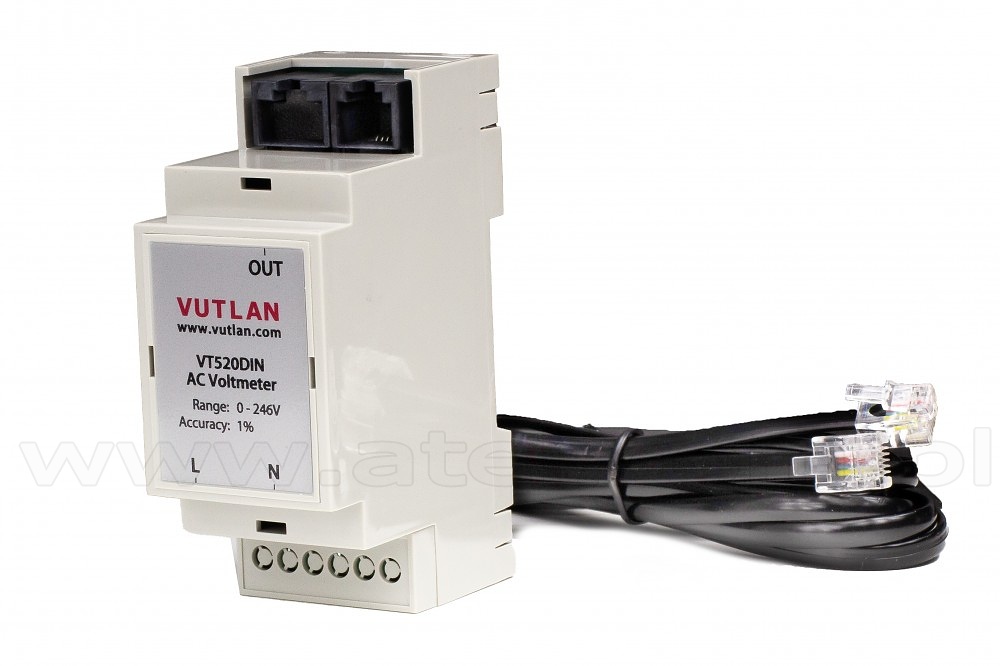
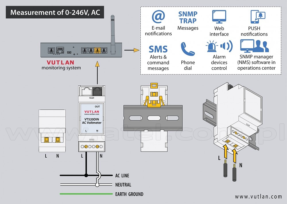
The sensor is used for the measurement of 0-246V, AC. It has a very high 1% accuracy. It can be used with any Vutlan monitoring system. DIN rail 35mm mounting.Voltage measured 0-246V AC Accuracy of measurement 1% Max. distance m 100m Net weight 125g Dimensions (HxWxD) 90.2×36.3×57.5mm
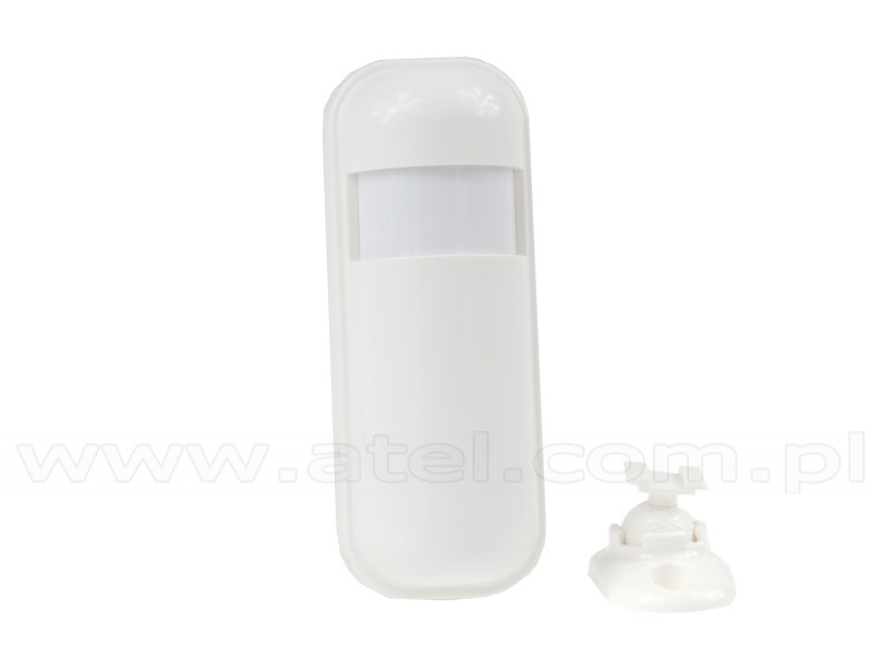
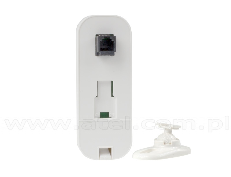
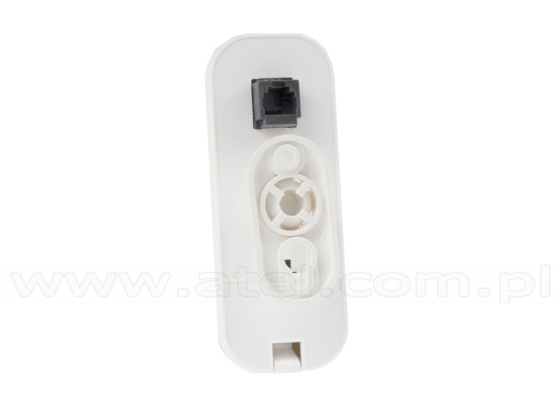
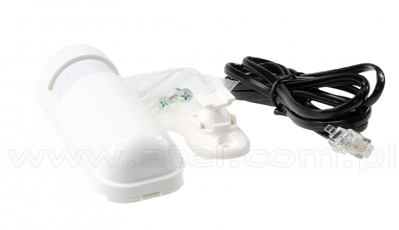
#03111Radar motion sensor (Vutlan VT572)
A microwave radar high-performance sensor is used for the detection of objects or human movement. This product is an indoor energy-saving high-sensitivity detector.
The scanned signal can penetrate plastic, glass, ceiling, wooden door, and thin walls.Technical specifications Detection angle 120° Sensing distance maximum is 8 meters Frequency Range 5.725GHz-5.875GHz Max. detection distance 100 m Features Installation On the bottom there is a mounting slot for fastening the sensor with a plastic bracket. Connection Motion sensor contains RJ-11 jack and is connected to an analog input of any system unit. Determination of sensor's type and connection occur automatically. To adjust sensitivity,
read manual. To change cable connection,
open the cover and read manual.Supply includes Sensor,
cable RJ11 4m,
holder
#08246Smoke sensor (Vutlan VT560)
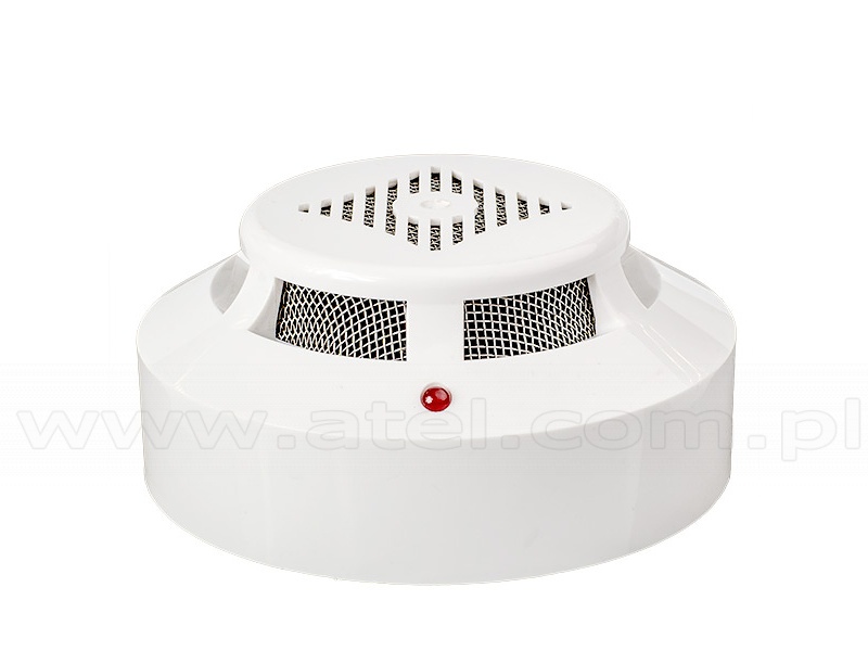
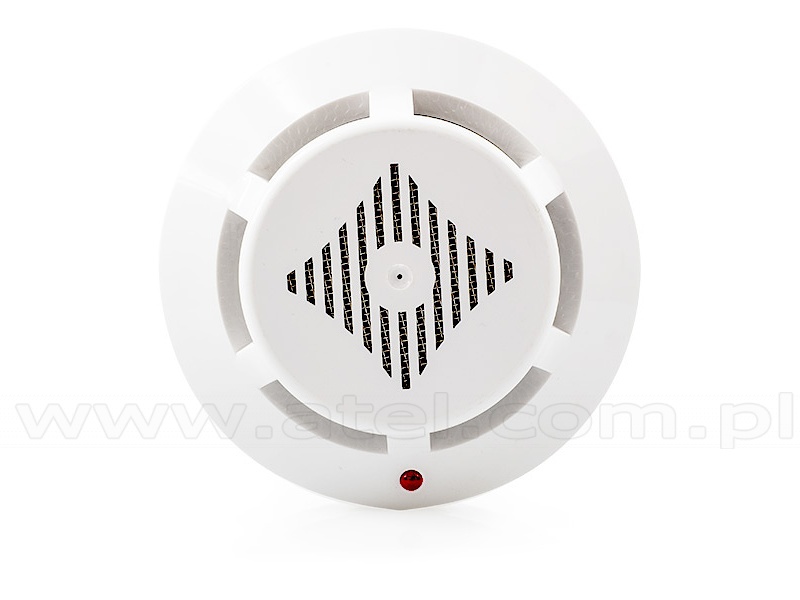
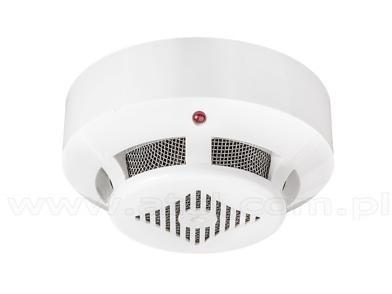
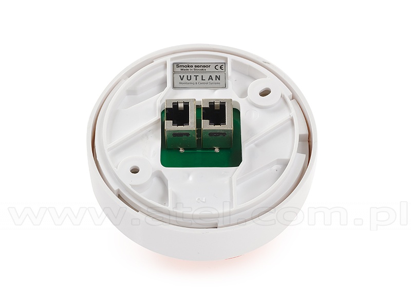
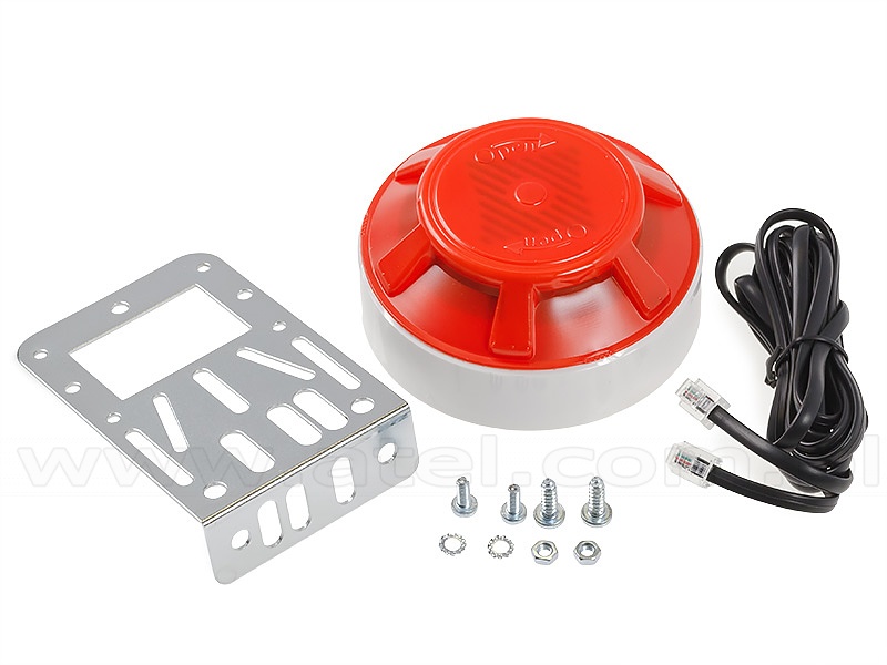
The sensor monitors occurrence of smoke.Technical specifications Sensitivity 0,05 - 0,2 db/m Features Installation On the bottom there are Ø5mm mounting holes for fastening the smoke sensor to the surface by 4.8×20mm screws or/and bracket and M4 screws. Connection Detector's jack RJ-11 is connected to an analog input of any system unit using patch-cable RJ-11. Determination of the sensor's type and connection occur automatically. The monitoring system allows to connect several smoke detectors into a linear circuit. For this purpose each detector has two jacks RJ-11 input and output. The first is connected to an analog input of the system unit using a patch-cable RJ-11,
the consequent is connected via patch-cable RJ-11 to an output of the first detector and so on. as one sensor with one address.Supply includes Detector,
4-wired cable RJ11 (2m),
2 screws and 2 nuts M4,
2 screws 4.8×20mm,
bracket,
double sided sticker.Net weight 290g Dimensions (LHW) Ø100×45 Max distance 150m
#08242Temperature sensor (Vutlan VT500)
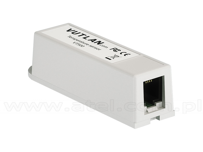
The sensor is made for measurement of temperature indoors.
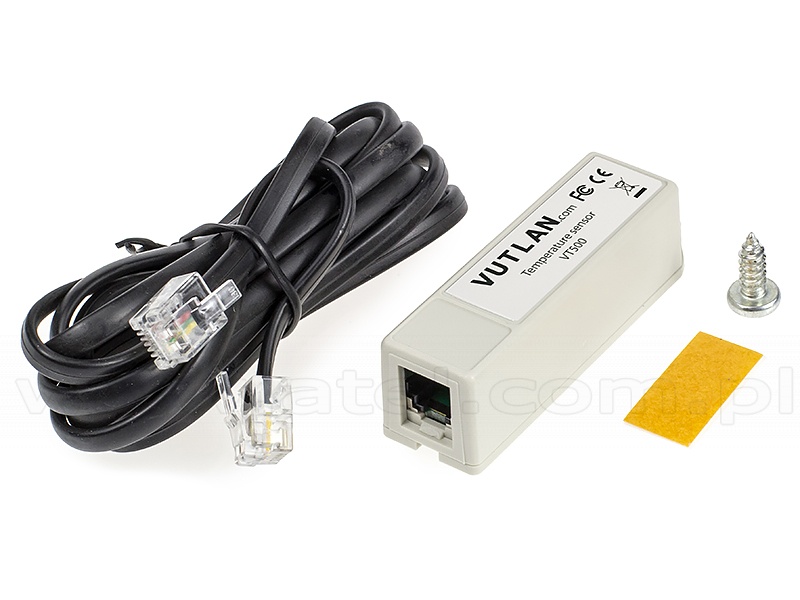
Measuring range: -10 ÷ 80°CTechnical specifications Operating temperature -10 ÷ 80°C Accuracy 1°C Features Installation On the bottom there is a ledge with Ø4.5mm and height 1mm and a Ø5mm mounting hole for fastening the sensor using a 4.8×16 mm screw. Connection Temperature sensor contains RJ-11 jack and is connected to an analog input of a system unit. Determination of type of sensor and connection occur automatically. Supply includes Sensor,
4-wired patch cable RJ11 (2m),
4.8×16mm screw,
double sided sticker.Net weight 50g Dimensions (LHW) 60×18×18mm Max distance 100m
- » CAN SENSORS#08295
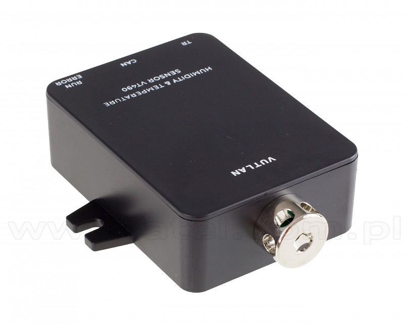
Humidity and temperature sensor (Vutlanl VT490)
Digital sensor made for monitoring temperature and humidity inside buildings, rack cabinets, etc.Technical specifications Measured temperature range -10 ÷ 80°C Accuracy ±0.4°C in –10 to 85 °C range Measured humidity range 0 - 95%RH Accuracy %RH ± 3% RH in 0 to 80% range Maximum distance from the appliance 225m Features Connection Sensor's jack RJ-12 is connected to CAN input of any system unit or to a CAN output of another sensor using RJ-12 patch cable. Determination of sensor's type and connection occur automatically. The system enables connecting multiple sensors to a linear layout. For this purpose,
each sensor is equipped with two RJ-11 input and output sockets.Net weight 160g Dimensions 68 × 47 x 26 mm
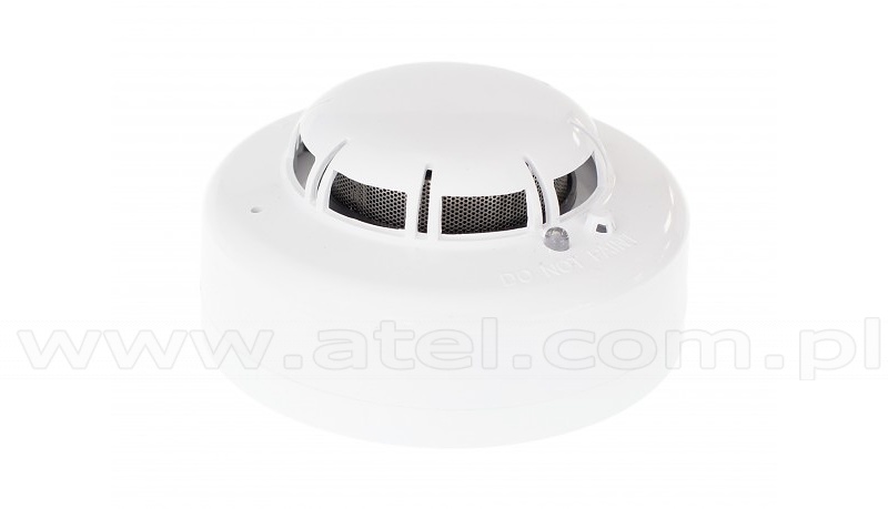
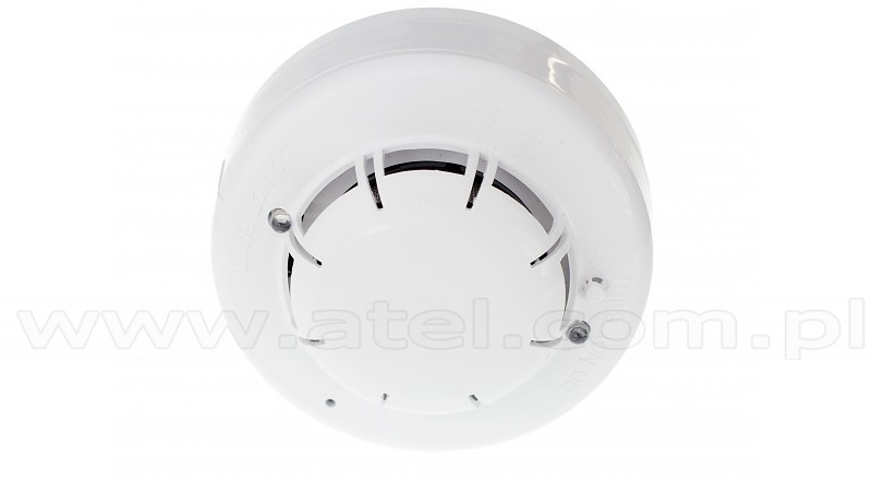
#08237Smoke, humidity and temperature sensor (Vutlan VT460)
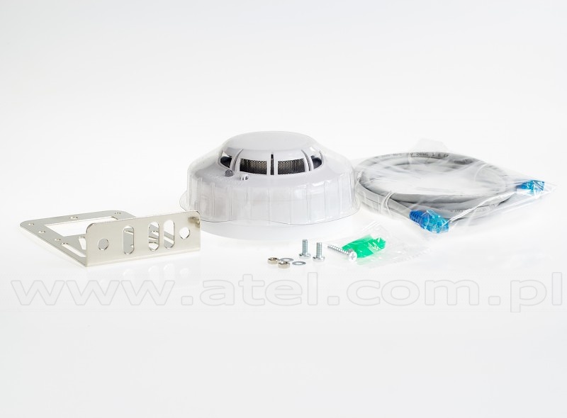
Digital sensor made for monitoring temperature and humidity and detecting smoke inside buildings, rack cabinets, etc.Technical specifications Smoke sensitivity 0,05 - 0,2 db/m Response time 10 sec Measured temperature range -10 to +75 °C Accuracy ±0.4°C in –10 to 85 °C range. Measured humidity range 0 - 95%. Accuracy %RH ± 3% RH in range of 0 - 80% Maximum distance from the appliance 225m Features Installation On the bottom there are mounting holes for fastening the smoke sensor to the surface using screws 4.8×20mm or/and bracket and M4 screws. Connection Sensor's jack RJ-12 is connected to CAN input of any system unit or to a CAN output of another sensor using RJ-11 patch cable. Determination of sensor's type and connection occur automatically. Monitoring system allows connection of up to 40 smoke sensors into a linear circuit. Set includes Sensor,
3-wired shielded patch cable RJ11 (2m),
bracket,
2 screws and 2 nuts M4,
2 screws 4.8×20mm,
double sided sticker.Net weight 310g Dimensions (LHW) Ø100×45mm
-






Page 6 of 12
|


